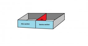
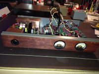
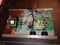
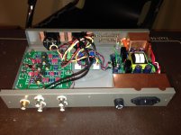
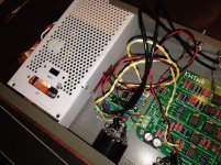
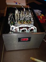
Thank you for advices. I already made some changes with Cu, but still waiting for Mu piece to arrive. For these how followed my enquiries, at the beginning I decided to integrate my Linkwitz into my sub, but unfortunately I realized it is not that easy. All RCAs are PCB soldered and I do not want to demolished OEM work. So, I made an external box with VU meters (VU meters are for fun). Please see attached pictures. I’ll share with the noise fight results when MU will be installed too.
Attachments
best thing split the box in 2
If one can do... make decent front like that... secondhandCDplayerwhithalfdecentserviceablebox cost £10
Keep trafo 1/2 a foot away.
If Ugot issue whit noise at line level U got problem somwhere no Mu metal can cure
If one can do... make decent front like that... secondhandCDplayerwhithalfdecentserviceablebox cost £10
Keep trafo 1/2 a foot away.
If Ugot issue whit noise at line level U got problem somwhere no Mu metal can cure
Attachments
Last edited:
What is this? 007 equipment?
Such arrangement is an excellent arrangement (a lot of thick cupper) for MC RIAA when signal level is tremendously low and device can pick up every type of interference easily.
In my case, I deal with line out (2V P2P) and I have no noise. I'm just trying to avoid some potential Magnetic, EMI or RF interference and unfortunately all AC and DC staff should be in one enclosure.
U quite right That is FDW single chip balanced MC RIAA probably one of the quietest MC stages I have
Right so U actualy doing Mu-metal not because of issiues but because there may be potential isues at line level (2V P2P)
I remember now same bloke of your side of the pond going for same extreme measures because "there may be things that we know that we don't know"
So U may need to get one of those FN9264-1-06 | Schaffner FN9264 Series 1A 250 V ac 400Hz Flange Mount EMI Filter, with Tab Terminals | Schaffner
And could also do whit DC Filter http://www.diyaudio.com/forums/powe...t-buzzing-toroid-transformers-what-right.html
And maybe change traffo for toroid type
Belt and braces and hold them tight just in case same joker sneack behind your back...
U're right and Yes, I over-eng in some cases. But, It is better than under-eng issue frequently found in the most commercial products after cost reduction steps to maintain desired margin.
About EMI/RFI modules, I had very bad experience with the AC Main entrance filters. I tested several models and got noticeable degradation in general sound presentation.
Maybe it is just me…
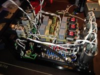
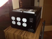
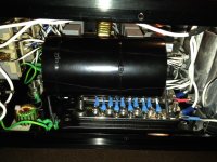
So, I decided to build Main AC conditioner by myself. Two forum guys helped me to finalize it. It is very different sound now and I like it a lot. With it and without it - it is like day and night differences.
See attached picture.
http://www.diyaudio.com/forums/power-supplies/246394-dc-blockers-mains-filters-6.html
Post #53
I wish I could find such small and PCB-mountable toroid. Everything what I see is much bigger. I need at least 8-9VAC and 150mA trany there.
I also used DC blocked in my several builds, particularly when I used huge toroids. But, DC blocker is treating mechanical noise caused by winding movement of toroids. Not my carnet case….
About EMI/RFI modules, I had very bad experience with the AC Main entrance filters. I tested several models and got noticeable degradation in general sound presentation.
Maybe it is just me…
So, I decided to build Main AC conditioner by myself. Two forum guys helped me to finalize it. It is very different sound now and I like it a lot. With it and without it - it is like day and night differences.
See attached picture.
http://www.diyaudio.com/forums/power-supplies/246394-dc-blockers-mains-filters-6.html
Post #53
I wish I could find such small and PCB-mountable toroid. Everything what I see is much bigger. I need at least 8-9VAC and 150mA trany there.
I also used DC blocked in my several builds, particularly when I used huge toroids. But, DC blocker is treating mechanical noise caused by winding movement of toroids. Not my carnet case….
Attachments
Last edited:
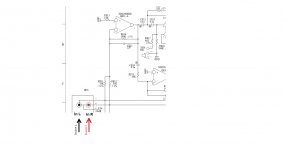
Hi Salas, I'm wondering why you chose a value of 47K for the res just before the RIAA network (I think it is R14, according to your 'PCB Guide')? As distinct from, say, 33K.
AIUI, it needs to be at least 10x the value of R13 - which 33K would be? Wouldn't 33K produce less loss in the RIAA network?
Thanks,
Andy
AIUI, it needs to be at least 10x the value of R13 - which 33K would be? Wouldn't 33K produce less loss in the RIAA network?
Thanks,
Andy
It was producing rounder rest of RIAA values and it was safely more than 44K (20x2.2k) for the input stage's 2.2k (R4) output impedance to can drive easily. 10x is good enough, 20x is best if able. To the contrary small values produce loss, but too high values contribute noise.
The RIAA bridge resistor directly influences the values of the rest passive RIAA components and any experiment towards lower or higher would demand recalculation and substitution of the whole filter network parts. I had experimented enough towards a good balance between loading, noise, and next stage drive ability before settled there, but the curious to change and listen to other values must keep in mind that the EQ will not work correctly when changing the bridge resistor value only (R14).
Guys, please accept my apology since I know this is not right forum for my subject, but I obviously can't fine such amount of gurus anywhere beside under Salas treat.
I’m trying to connect one sub to two sources. When I connect one of two source individually – no issue. Connecting both – ground loop noise. I realized I need 1:1 isolation trany at least to isolate one source. Do not think that series Ele cap will help me to treat loop as DC stopper. So, can you advise me a relatively inexpensive and small isolation trany for that propose. It should be capable to pass through 20-250Hz. Thank you a lot.
I’m trying to connect one sub to two sources. When I connect one of two source individually – no issue. Connecting both – ground loop noise. I realized I need 1:1 isolation trany at least to isolate one source. Do not think that series Ele cap will help me to treat loop as DC stopper. So, can you advise me a relatively inexpensive and small isolation trany for that propose. It should be capable to pass through 20-250Hz. Thank you a lot.
Attachments
Last edited:
- Home
- Source & Line
- Analogue Source
- Simplistic NJFET RIAA