What's the tolerance and/or accuracy of this 14948pF?..........C2 is (Vishay 15nF from my mini-kit) -> 14.948nF at 10kHz.......
+-1pF, or +-10pF, or +-100pF, or +-1000pF?
I would guess (no better than that) that the test frequency for determining the capacitance should be the turn over frequency in the filter it is installed in................Film caps are nominal at 1kHz also even if we talk bigger uF range types like those for loudspeaker crossovers or output coupling, PSU bypass etc.
You will be alright even when reaching 15.15nF+ value, more importantly stay matched enough between channels, say no more than 0.5% difference.
i.e. where the phase is 45degrees and the impedance equals the resistance in the RC filter.
What's the tolerance and/or accuracy of this 14948pF?
+-1pF, or +-10pF, or +-100pF, or +-1000pF?
Attachments
Congrats Salas. Indeed FS is no slough at all. I am enjoying my every day.
Quan
Its Erlend's build effort that won foremost, but I am happy I did not let builders down with a problematic to put together or below average design recommendation. Thanks for your kind words.
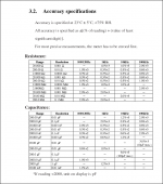
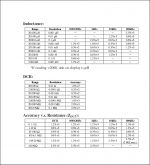
Seems like meeting its spec in practice or even exceeding it, watch this vid:that's a very good instrument.
20000 count and accuracy to +-0.3%+2digits puts well ahead of most.
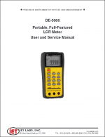
IET DE-5000 ESR MEASUREMENT - YouTube
The rival is TH2822 which comes in 1,10,100kHz models: http://kuzyatech.com/wp-content/uploads/2013/04/Tonghui_TH2822A_DS.pdf
40000 counts, 0.25% basic accuracy and higher resolution secondary display for sorting low dissipation factor caps easier, also nice big long Kelvin clips, mini USB logging. I would recommend you study the specs and features in detail regarding your needs first on both models. Then look for pricing, that varies widely for partial to full accessory package offers between international dealers.
Look for DER EE OEM version of the DE-5000 and find a fully featured with all probes and accessories offer to compare. There are some available in very good prices from Japan lately.
With a bit of luck I'll have the PSU done tomorrow before the Patriots-Broncos kickoff ") Playoffs are wreaking havoc on my construction schedule, plus daughter is having a tea party tomorrow afternoon (actual tea, not US politics).
Playoffs are wreaking havoc on my construction schedule, plus daughter is having a tea party tomorrow afternoon (actual tea, not US politics).


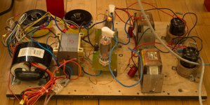
Here's detail of my dropping resistor lash-up. Hitting exactly 50V at about 100mA, but I'm planning another R and C in the other chassis:

So tomorrow I'll drill and install a chassis ground screw, and work on the back panel. Fitting the power entry module is the hardest part, especially in a steel chassis. All the rest are round holes, which are easy .
Playoffs are wreaking havoc on my construction schedule, plus daughter is having a tea party tomorrow afternoon (actual tea, not US politics).
Here's detail of my dropping resistor lash-up. Hitting exactly 50V at about 100mA, but I'm planning another R and C in the other chassis:
So tomorrow I'll drill and install a chassis ground screw, and work on the back panel. Fitting the power entry module is the hardest part, especially in a steel chassis. All the rest are round holes, which are easy
.Looks orderly and compact. You used a dummy load for 100mA draw I assume. Aim for circa 47VDC on your final real consumptions per channel after your further local RC. Achieving exactly matched raw DC value per channel input will not be important. Don't spend too much time on that.
This weekend i finalised an experiment i have been planning for a while - using tube rectification for low voltage SS circuitry. In short: it wasn't successful
The gist of it was replacing the MUR860 bridge in the CLC filter with half-way rectification provided by 6D22S.
At input AC around 60v there is around 50v dc after the rectifier with a first cap of 100uF and current draw of 100mA. A common mode 2 x 4H choke follows and a 10mF cap for a final DC voltage around 47v.
Electrically all is fine, but the sound is flat and lacking dynamics. My guess is that the 6D22s is not so great at such a low voltage. A suitable course of action would probably be to raise the AC above 150v and burn the excess dc into a couple of RC filters preceding the chokes. Don't have sufficient incentive to try it out though.
Attachments
- Home
- Source & Line
- Analogue Source
- Simplistic NJFET RIAA