Has anyone tried paralleling the LDRs with resistors?
Is there such a thing as too low of an impedance, for an attenuator?
For example, if the shunt LDR is paralleled with 10k and the series LDR is paralleled with 9.1k (equalizes LDR resistances assuming 100k load resistance), then the input and output resistances vary between near zero and about 5.6k, and the resistance seen between the input and ground varies between about 5.7k and 6.8k. Also, the attenuation versus pot setting looks a lot more linear, and still varies from 98.5% to 0.9%, and the input and output impedances also look more linear.
Hel-lo...! THAT's interesting... Without the 10k & 9.1k parallel resistors, the input-to-gnd resistance varies downward and then upward. But WITH the parallel resistors, it varies upward then downward. That seems to imply that somewhere between infinite resistances and 10k/9.1k, there might be a set of resistances that make the input-to-ground resistance (versus pot position) almost perfectly flat!
Let's just see... (Wow, simulation is GREAT for checking this type of stuff.)
YUP. With 24K in parallel with the shunt LDR and 19k in parallel with the series LDR, the input-to-gnd resistance stays within 50 Ohms of 8.4k, except for a small peak at the pot's midpoint, where it rises to 8.5k. (Also, with this setup, the input and output impedances range between about 8.5k and near zero, and the attenuation ranges from 99.96% to 1.06%.)
Note that for other load impedances (i.e. different than 100k Ohms), the parallel resistance's values would need to be different. I used roughly the 100k load resistance in parallel with the 24k Ohms (which was quickly found through trial and error) to calculate the equivalent 19.35k for the series LDR's parallel resistance, and then tweaked the 19.35k down to 19k to get a flatter and more symmetrical resistance plot. [I just now did this and haven't checked to see if it can be optimized further.] It looks like the standard values of 24.3k and 19.1k work almost as well. Anyway, for a 50K load resistance, for example, it looks like 30k || shunt LDR and 18.4k || series LDR gives similar results. I guess for a "universal" version, unfortunately, you'd need a 4-pole multi-throw switch with the optimal resistances for different load input impedances. (Note, too, that different "grades" of optocouplers, with different resistance ranges, might also need different parallel resistance values.) [Edit: I guess it MIGHT also be possible to use a dual pot (wired as attenuators) for each channel's parallel resistances, with a resistance equal to the load impedance (another pot?) in parallel with the one for the series LDR. It might be hell to calibrate, that way. But at least it would theoretically cover most cases. (Or, use LDRs for the parallel resistances, and have a digital system that could calibrate their LED curents for any load impedance.") ]
]
To simulate the above, I used a setup that is very similar to the LTspice stuff that I posted a link to, previously, except that I had eliminated one of the pots and wired the 5v supply to the wiper of the remaining one and took the sources for the optos' LEDs from the ends of the pot, as I think I saw mentioned by georghifi, here, recently. I had 50 Ohms (simulated source) in series with the input and 100k from output to ground (simulated load). I connected a 1 Amp current source to the input, so the voltage at the input would equal the resistance to ground, there (just being lazy). I also used a sweeptime (for the pot) of 3 seconds, to get what looks like good-enough accuracy.
After writing all of that, I guess I should ask just how valuable it might actually BE, for the resistance from input to ground to stay almost constant. (If it doesn't matter much, at least the simulations didn't take long.)
As a side-benefit, it SEEMS like the parallel resistances might somewhat-alleviate the problems caused by slightly-mismatched optocouplers, making the matching somewhat less-critical.
Is there such a thing as too low of an impedance, for an attenuator?
For example, if the shunt LDR is paralleled with 10k and the series LDR is paralleled with 9.1k (equalizes LDR resistances assuming 100k load resistance), then the input and output resistances vary between near zero and about 5.6k, and the resistance seen between the input and ground varies between about 5.7k and 6.8k. Also, the attenuation versus pot setting looks a lot more linear, and still varies from 98.5% to 0.9%, and the input and output impedances also look more linear.
Hel-lo...! THAT's interesting... Without the 10k & 9.1k parallel resistors, the input-to-gnd resistance varies downward and then upward. But WITH the parallel resistors, it varies upward then downward. That seems to imply that somewhere between infinite resistances and 10k/9.1k, there might be a set of resistances that make the input-to-ground resistance (versus pot position) almost perfectly flat!
Let's just see... (Wow, simulation is GREAT for checking this type of stuff.)
YUP. With 24K in parallel with the shunt LDR and 19k in parallel with the series LDR, the input-to-gnd resistance stays within 50 Ohms of 8.4k, except for a small peak at the pot's midpoint, where it rises to 8.5k. (Also, with this setup, the input and output impedances range between about 8.5k and near zero, and the attenuation ranges from 99.96% to 1.06%.)
Note that for other load impedances (i.e. different than 100k Ohms), the parallel resistance's values would need to be different. I used roughly the 100k load resistance in parallel with the 24k Ohms (which was quickly found through trial and error) to calculate the equivalent 19.35k for the series LDR's parallel resistance, and then tweaked the 19.35k down to 19k to get a flatter and more symmetrical resistance plot. [I just now did this and haven't checked to see if it can be optimized further.] It looks like the standard values of 24.3k and 19.1k work almost as well. Anyway, for a 50K load resistance, for example, it looks like 30k || shunt LDR and 18.4k || series LDR gives similar results. I guess for a "universal" version, unfortunately, you'd need a 4-pole multi-throw switch with the optimal resistances for different load input impedances. (Note, too, that different "grades" of optocouplers, with different resistance ranges, might also need different parallel resistance values.) [Edit: I guess it MIGHT also be possible to use a dual pot (wired as attenuators) for each channel's parallel resistances, with a resistance equal to the load impedance (another pot?) in parallel with the one for the series LDR. It might be hell to calibrate, that way. But at least it would theoretically cover most cases. (Or, use LDRs for the parallel resistances, and have a digital system that could calibrate their LED curents for any load impedance.
]To simulate the above, I used a setup that is very similar to the LTspice stuff that I posted a link to, previously, except that I had eliminated one of the pots and wired the 5v supply to the wiper of the remaining one and took the sources for the optos' LEDs from the ends of the pot, as I think I saw mentioned by georghifi, here, recently. I had 50 Ohms (simulated source) in series with the input and 100k from output to ground (simulated load). I connected a 1 Amp current source to the input, so the voltage at the input would equal the resistance to ground, there (just being lazy). I also used a sweeptime (for the pot) of 3 seconds, to get what looks like good-enough accuracy.
After writing all of that, I guess I should ask just how valuable it might actually BE, for the resistance from input to ground to stay almost constant.
(If it doesn't matter much, at least the simulations didn't take long.)As a side-benefit, it SEEMS like the parallel resistances might somewhat-alleviate the problems caused by slightly-mismatched optocouplers, making the matching somewhat less-critical.
Peter,
thanks for the CCS circuit - I tried it and although I need to make a few changes ( i.e. better quality series resistors ) I quite like the sound. I think I am hearing the lower distortion that someone posted a picture of.
Do you think putting a few bypass caps across the pot will overcome the problem of DC flowing through the contact ? - It will be a while before I get a stepped attenuator
mike
Sorry if I seem to be 'hogging' the thread, for the moment. This stuff is getting interesting. (It's been quiet, for the last few days. Is everyone off having fun with the LTspice attenuator simulations? Or maybe breadboarding attenuators with resistances in parallel with the LDRs?
Obviously, many sources could have serious problems driving an impedance that is too low. Most sources can probably drive an impedance down to 2 kOhms. But what is optimal, in terms of distortion, etc? I guess that that depends on the particular source. (There is some discussion of that, in Walt Jung's "Op Amp Applications Handbook", on pages 6.48 through 6.64 of section 6, here: http://www.analog.com/library/analogDialogue/archives/39-05/Web_Ch6_final_I.pdf .) The load's input circuitry's configuration is also affected by having the attenuator's shunt impedance connected to it. Another consideration is cables. In one sense, a lower impedance would usually be better, if followed by a cable, because of the cable's capacitance, and the filter formed by the attenuator's series impedance and the following cable's capacitance.
Apparently, there is no universally-best impedance goal, for all systems. However, it seems that the majority of commercially-available passive attenuators have about 10k Ohms of total impedance (i.e. series plus shunt resistance), although there is at least one model with a 1k impedance.
Well, one of the main ideas was to eliminate potentiometers and switch contacts, etc, from the signal path. To remain true to that goal, it would, unfortunately, probably be necessary to either solder-in fixed resistors (or use some un-objectionable connection method to enable swapping them in and out, more easily), for EACH particular source's input impedance, or use LDRs for the parallel resistances, which would necessitate some added complexity. In any case, it looks like modifying the Lightspeed IIx, or making any universally-applicable (i.e single-version) commercial LDR attenuator product that could take _optimal_ advantage of using linearizing resistances in parallel with the LDRs, for diverse load impedances, might be a challenge. (Enabling the attenuator to automatically adjust itself to have a user-selectable total impedance would be even more of a challenge, but might also be desirable.)
It looks like it IS very important to try to have the input impedance stay as constant as possible, as the attenuation is varied.
Regarding using parallel-to-LDR linearizing resistances with a range of different load impedances, and with different total attenuator impedances, I did a few more simulations, just to see what might be easily achievable.
In this case, I wanted to see if I could use previously-calculated fixed parallel resistances for the series and shunt LDRs, with an additional variable parallel resistance for the series LDR, to try to be able to 'automatically' adjust the linearization for various load impedances (by keeping the || Rs' ratio constant).
The variable parallel resistances for the series LDRs might be two more optocouplers' LDRs, for example, with a potentiometer or rotary switch to select their resistances, based on the load impedance.
In one case, I added 24k in parallel with each shunt LDR and about 23.6k in parallel with each series LDR, noting that 23.6k paralleled with 100k is the 19.1k that I had earlier found to work well, for a 100k load impedance (but which has not really been optimized, yet). I then added an additional variable resistance in parallel with each series LDR, which was automatically kept equal to the load impedance, as I had the simulator step the load impedance from 25k to 225k, in 50k steps.
For such a simple scheme, it worked fairly well! Not including the 25k load case, the average input impedance ranged between roughly 8.1k and 8.7k (as the attenuation went from max to min, for each of the four load impedances). The impedance variation, for the four load impedance cases (75k, 125k, 175k, and 225k), ranged from about 149 Ohms to about 269 Ohms. The impedances also varied quite symmetrically wrt the attenuation midpoint. (For the original 100k case, the impedance range was about 143.5 Ohms, varying within a range from about 8.43k to about 8.29k, with an average of 8.33k. [And ignoring the peak during the middle 10% of the attenuation range, the variation range was only about 84 Ohms; about 1%.]) For the 25k load, it was somewhat worse. In that case, the impedance varied between about 6.67k and about 7.48k (an 810-Ohm range), averaging around 7k. Still not too bad.
For reference, I also simulated a "standard" Lightspeed IIx configuration, with the same load-impedance steps. Not including the 25k load case, the input impedance variation range was between about 4.4k and about 4.7k (varying from about 14.9k to between 10.2k and 10.55k, for the four load impedances). With the 25k load, the impedance ranged from about 14.9k to about 9k (a 5.9k impedance-variation range), and was relatively lopsided toward having its lowest impedances on the less-attenuation side of the plot. (For the 100k load case, the impedance goes from about 14.9k, down to about 10.3k, and then back up to about 12.7k (a 4.6k variation range), as attenuation is varied from max to min, with an average impedance of about 11.7k.)
From the above data, it is seen that the improvement in the input impedance versus attenuation-setting plot's "flatness", using parallel-to-LDRs linearizing resistances, is significant. For a 100k load, the variation range of the input impedance is reduced from 4.6k Ohms (with 11.7k average) to 143.5 Ohms (with 8.33k average). That's an impedance-variation-range reduction from about 39% to about 1.7%.
gootee said:Has anyone tried paralleling the LDRs with resistors?
Is there such a thing as too low of an impedance, for an attenuator?
Obviously, many sources could have serious problems driving an impedance that is too low. Most sources can probably drive an impedance down to 2 kOhms. But what is optimal, in terms of distortion, etc? I guess that that depends on the particular source. (There is some discussion of that, in Walt Jung's "Op Amp Applications Handbook", on pages 6.48 through 6.64 of section 6, here: http://www.analog.com/library/analogDialogue/archives/39-05/Web_Ch6_final_I.pdf .) The load's input circuitry's configuration is also affected by having the attenuator's shunt impedance connected to it. Another consideration is cables. In one sense, a lower impedance would usually be better, if followed by a cable, because of the cable's capacitance, and the filter formed by the attenuator's series impedance and the following cable's capacitance.
Apparently, there is no universally-best impedance goal, for all systems. However, it seems that the majority of commercially-available passive attenuators have about 10k Ohms of total impedance (i.e. series plus shunt resistance), although there is at least one model with a 1k impedance.
For example, if the shunt LDR is paralleled with 10k and the series LDR is paralleled with 9.1k (equalizes LDR resistances assuming 100k load resistance), then the input and output resistances vary between near zero and about 5.6k, and the resistance seen between the input and ground varies between about 5.7k and 6.8k. Also, the attenuation versus pot setting looks a lot more linear, and still varies from 98.5% to 0.9%, and the input and output impedances also look more linear.
Hel-lo...! THAT's interesting... Without the 10k & 9.1k parallel resistors, the input-to-gnd resistance varies downward and then upward. But WITH the parallel resistors, it varies upward then downward. That seems to imply that somewhere between infinite resistances and 10k/9.1k, there might be a set of resistances that make the input-to-ground resistance (versus pot position) almost perfectly flat!
Let's just see... (Wow, simulation is GREAT for checking this type of stuff.)
YUP. With 24K in parallel with the shunt LDR and 19k in parallel with the series LDR, the input-to-gnd resistance stays within 50 Ohms of 8.4k, except for a small peak at the pot's midpoint, where it rises to 8.5k. (Also, with this setup, the input and output impedances range between about 8.5k and near zero, and the attenuation ranges from 99.96% to 1.06%.)
Note that for other load impedances (i.e. different than 100k Ohms), the parallel resistance's values would need to be different. I used roughly the 100k load resistance in parallel with the 24k Ohms (which was quickly found through trial and error) to calculate the equivalent 19.35k for the series LDR's parallel resistance, and then tweaked the 19.35k down to 19k to get a flatter and more symmetrical resistance plot. [I just now did this and haven't checked to see if it can be optimized further.] It looks like the standard values of 24.3k and 19.1k work almost as well. Anyway, for a 50K load resistance, for example, it looks like 30k || shunt LDR and 18.4k || series LDR gives similar results. I guess for a "universal" version, unfortunately, you'd need a 4-pole multi-throw switch with the optimal resistances for different load input impedances. (Note, too, that different "grades" of optocouplers, with different resistance ranges, might also need different parallel resistance values.) [Edit: I guess it MIGHT also be possible to use a dual pot (wired as attenuators) for each channel's parallel resistances, with a resistance equal to the load impedance (another pot?) in parallel with the one for the series LDR. It might be hell to calibrate, that way. But at least it would theoretically cover most cases. (Or, use LDRs for the parallel resistances, and have a digital system that could calibrate their LED curents for any load impedance.
Well, one of the main ideas was to eliminate potentiometers and switch contacts, etc, from the signal path. To remain true to that goal, it would, unfortunately, probably be necessary to either solder-in fixed resistors (or use some un-objectionable connection method to enable swapping them in and out, more easily), for EACH particular source's input impedance, or use LDRs for the parallel resistances, which would necessitate some added complexity. In any case, it looks like modifying the Lightspeed IIx, or making any universally-applicable (i.e single-version) commercial LDR attenuator product that could take _optimal_ advantage of using linearizing resistances in parallel with the LDRs, for diverse load impedances, might be a challenge. (Enabling the attenuator to automatically adjust itself to have a user-selectable total impedance would be even more of a challenge, but might also be desirable.)
To simulate the above, I used a setup that is very similar to the LTspice stuff that I posted a link to, previously, except that I had eliminated one of the pots and wired the 5v supply to the wiper of the remaining one and took the sources for the optos' LEDs from the ends of the pot, as I think I saw mentioned by georghifi, here, recently. I had 50 Ohms (simulated source) in series with the input and 100k from output to ground (simulated load). I connected a 1 Amp current source to the input, so the voltage at the input would equal the resistance to ground, there (just being lazy). I also used a sweeptime (for the pot) of 3 seconds, to get what looks like good-enough accuracy.
After writing all of that, I guess I should ask just how valuable it might actually BE, for the resistance from input to ground to stay almost constant.
It looks like it IS very important to try to have the input impedance stay as constant as possible, as the attenuation is varied.
As a side-benefit, it SEEMS like the parallel resistances might somewhat-alleviate the problems caused by slightly-mismatched optocouplers, making the matching somewhat less-critical.
Regarding using parallel-to-LDR linearizing resistances with a range of different load impedances, and with different total attenuator impedances, I did a few more simulations, just to see what might be easily achievable.
In this case, I wanted to see if I could use previously-calculated fixed parallel resistances for the series and shunt LDRs, with an additional variable parallel resistance for the series LDR, to try to be able to 'automatically' adjust the linearization for various load impedances (by keeping the || Rs' ratio constant).
The variable parallel resistances for the series LDRs might be two more optocouplers' LDRs, for example, with a potentiometer or rotary switch to select their resistances, based on the load impedance.
In one case, I added 24k in parallel with each shunt LDR and about 23.6k in parallel with each series LDR, noting that 23.6k paralleled with 100k is the 19.1k that I had earlier found to work well, for a 100k load impedance (but which has not really been optimized, yet). I then added an additional variable resistance in parallel with each series LDR, which was automatically kept equal to the load impedance, as I had the simulator step the load impedance from 25k to 225k, in 50k steps.
For such a simple scheme, it worked fairly well! Not including the 25k load case, the average input impedance ranged between roughly 8.1k and 8.7k (as the attenuation went from max to min, for each of the four load impedances). The impedance variation, for the four load impedance cases (75k, 125k, 175k, and 225k), ranged from about 149 Ohms to about 269 Ohms. The impedances also varied quite symmetrically wrt the attenuation midpoint. (For the original 100k case, the impedance range was about 143.5 Ohms, varying within a range from about 8.43k to about 8.29k, with an average of 8.33k. [And ignoring the peak during the middle 10% of the attenuation range, the variation range was only about 84 Ohms; about 1%.]) For the 25k load, it was somewhat worse. In that case, the impedance varied between about 6.67k and about 7.48k (an 810-Ohm range), averaging around 7k. Still not too bad.
For reference, I also simulated a "standard" Lightspeed IIx configuration, with the same load-impedance steps. Not including the 25k load case, the input impedance variation range was between about 4.4k and about 4.7k (varying from about 14.9k to between 10.2k and 10.55k, for the four load impedances). With the 25k load, the impedance ranged from about 14.9k to about 9k (a 5.9k impedance-variation range), and was relatively lopsided toward having its lowest impedances on the less-attenuation side of the plot. (For the 100k load case, the impedance goes from about 14.9k, down to about 10.3k, and then back up to about 12.7k (a 4.6k variation range), as attenuation is varied from max to min, with an average impedance of about 11.7k.)
From the above data, it is seen that the improvement in the input impedance versus attenuation-setting plot's "flatness", using parallel-to-LDRs linearizing resistances, is significant. For a 100k load, the variation range of the input impedance is reduced from 4.6k Ohms (with 11.7k average) to 143.5 Ohms (with 8.33k average). That's an impedance-variation-range reduction from about 39% to about 1.7%.
Mike,
Great that you took the plunge! Off course the quality of series resistors is quite important. But everything should sound a lot cleaner and more natural right away.
If you have no problems with crackling pots then you are lucky. Caps across the pots could help but I didn’t try it because I had the DACT available.
Peter
mikelm said:I quite like the sound. I think I am hearing the lower distortion that someone posted a picture of. mike
Actually Mike, if you look at the -5db to -10db level point, which is very close to the level for normal listening with a Red-Book 2v CD source, you will see in the graphs on posts 1008 and 1009, that the series & shunt LDR's are almost at -100db THD, compared to series resistor/shunt LDR which is only at -45db THD.
This is why all my early commercial MK1 (resistor/LDR) Lightspeed Attenuators were recalled and converted to the much perfered better sounding MKII (LDR/LDR) Lightspeed Attenuators, which as a by-product has a more constant input and output impedance compared to the MK1, which CD/DACS and Power-Amps seemed to like better.
So at normal listening levels with CD as the source, you are hearing double the distortion with series resistor/shunt LDR than when Series LDR/Shunt LDR are used, maybe you like the extra 2H distortion in your sound, who knows?
Cheers George
Within certain limits I don’t care to much for distortion figures. It is far more interesting how it sounds. If you want to achieve high end performance of your gear it is better to spend your time by listening to various solutions than just to theorize and judge a solution. Of course everything has an explanation, but I have learned the most by trying configurations. It’s a bit the other way around. Gain knowledge by listening and try to explain things after, and try to use your thus gained knowledge in other area’s.
It’s a bit bland to judge from an easy chair that someone likes 2H distortion, without tying / listening to what he did. If don’t want to try it, that’s okay. But then you are not in the position to judge it either.
It’s a bit bland to judge from an easy chair that someone likes 2H distortion, without tying / listening to what he did. If don’t want to try it, that’s okay. But then you are not in the position to judge it either.
> if you look at the -5db to -10db level point, which is very close to the level for normal listening with a Red-Book 2v CD source, .... you are hearing double the distortion with series resistor/shunt LDR than when Series LDR/Shunt LDR are used .....
Can I assume 20dB power amp gain, no preamp or unity gain, & 85dB speakers ?
How does it look if we operate at -16dB or beyond at the attenuator ?
Thanks,
Patrick
Can I assume 20dB power amp gain, no preamp or unity gain, & 85dB speakers ?
How does it look if we operate at -16dB or beyond at the attenuator ?
Thanks,
Patrick
pietjers said:Within certain limits I don’t care to much for distortion figures. It is far more interesting how it sounds. If you want to achieve high end performance of your gear it is better to spend your time by listening to various solutions than just to theorize and judge a solution. Of course everything has an explanation, but I have learned the most by trying configurations. It’s a bit the other way around. Gain knowledge by listening and try to explain things after, and try to use your thus gained knowledge in other area’s.
It’s a bit bland to judge from an easy chair that someone likes 2H distortion, without tying / listening to what he did. If don’t want to try it, that’s okay. But then you are not in the position to judge it either.
They (MK1&MKII) were first judged with listening tests by myself and a few Audio Society members if you care to read back through the posts, and then backed up with the measurements.
And as far as judging that someone likes 2H, read again, I said maybe.
EUVL said:> if you look at the -5db to -10db level point, which is very close to the level for normal listening with a Red-Book 2v CD source, .... you are hearing double the distortion with series resistor/shunt LDR than when Series LDR/Shunt LDR are used .....
Can I assume 20dB power amp gain, no preamp or unity gain, & 85dB speakers ?
How does it look if we operate at -16dB or beyond at the attenuator ?
Thanks,
Patrick
I have taken it up much further in volume and listened with no ill effects, but I prefer to listen at normal to loud levels on my system, which happens to be in the -5 to -10 db range as with most systems I have encountered. I must admit at very low levels I do find it flat, probaly need a good old fashioned active loudness switch.
Cheers George
georgehifi said:Actually Mike, if you look at the -5db to -10db level point, which is very close to the level for normal listening with a Red-Book 2v CD source, you will see in the graphs on posts 1008 and 1009, that the series & shunt LDR's are almost at -100db THD, compared to series resistor/shunt LDR which is only at -45db THD.
Perhaps we're looking at different graphs.
georgehifi said:So at normal listening levels with CD as the source, you are hearing double the distortion with series resistor/shunt LDR than when Series LDR/Shunt LDR are used, maybe you like the extra 2H distortion in your sound, who knows?
1543's graphs show 3rd harmonic
I'm sorry to post another very long message. This will probably be the last one, unless someone else gets interested.
-----
THIS MIGHT BE USEFUL:
Going back to the first 'linearized' attenuator test setup, that I described in my last post, I wanted to see what happened if the variable resistances (the ones placed in parallel with the series LDRs, which, back then, were automatically changed to be kept equal to the load resistance) were kept FIXED, instead, at the nominal 100k Ohms, since, if it worked OK, that would enable a very simple implementation, using only one fixed resistance in parallel with each LDR, i.e. 24k in parallel with the shunt LDR, and something like 18.75k in parallel with the series LDR, if initially optimized (very roughly, in this case) for a 100k load impedance.
It actually still looks pretty good, that way, especially when compared to not using ANY linearizing resistances!
Below are the impedance extremes (from LTspice simulation), for the five test loads (25k to 225k @ 50k per step) and for the 100k-load 'nominal' case, plus a 1Meg-load case: [The percent figures are the variation ranges' percents of 8.31k. (They should probably more-properly be compared to their own average impedances. But stepped plots don't allow integration or averaging, in LTspice, and I was too lazy to run them all again, individually.)]
In my last post, it looks like I gave the wrong parallel resistance for the series LDR. It should have been about 23.077k, instead of 23.6k. It gives about 18.75k when paralleled by 100k Ohms.
So, just to be clear: The nominal total resistance that I used in parallel with the series LDR, for the 100k-load case, was 18.75k. And in parallel with the shunt LDR, I had 24k. And those are also the same (fixed) resistances that were used to obtain the simulation results that are in the table, directly above.
By the way, from the data above, it looks like initially optimizing for a somewhat-lower (than 100k) nominal load resistance might be able to equalize the impedance variation ranges of the low end and the high end, if improvement is desired for the lower load impedances.
-----
Comparing the results in the table above, from using fixed parallel-to-LDR resistances, to the earlier results from using one fixed resistor to parallel each LDR plus a variable resistance (kept equal to the load resistance) in parallel with each series LDR, I got the following comparison table: [Note that I DID re-run each load-impedance case, individually, and also tried to measure a little more accurately by using full-screen plots, and have used each run's own average impedance to calculate the percentages in the table below, as 100(max impedance - min impedance)/(average impedance). The Range and AVG figures have units of Ohms. The attenuation-control potentiometer was swept from end to end over a 3-second period. Edit: I added a third column, with results for NO parallel resistances, i.e. the basic Lightspeed MkII configuration.]
Since fixed-value parallel resistors would be relatively easy to add, that seems to be worth trying in hardware.
-----
I tried the same thing (parallel-to-LDRs 'linearizing' resistances; see my previous post), but with a '5k attenuator' configuration. To get about 5K Ohms total (series + shunt) attenuator impedance (including the new parallel resistances), I simply changed the supply voltage from 5v to 6v.
Then I first had to try to find nearly-optimal values for fixed parallel resistances for the series and shunt LDRs, for a 100k load (optimal in the sense that they provide the flattest input-to-ground impedance plot, with the least input impedance variation as the attenuation was varied from max to min).
(In case someone wants to try it who is not very familiar with LTspice, here is one method: ) To do that 'pseudo-optimization', I placed a resistance, with value {RP} (i.e. Right-click on a resistor and enter {RP} in the Value field. Note that the curly braces are mandatory.), in parallel with each of the series and shunt LDRs, and also added a 100k resistor in parallel with each series LDR (to equalize the parallel resistances, since 100k load was already in parallel with the RP across the shunt LDR). Then I used a spice '.step' directive to step the RP value, coarsely over a broad range at first, looking for the RP value where the input impedance plot changed from 'concave up' to 'concave down'. e.g. .step param RP 1k 101k 20k, to step RP from 1k to 101k in 20k steps. Then, seeing that the desired value was somewhere between 1k and 20k, I narrowed the search, e.g. .step param RP 1k 21k 5k, iterating like that until the steps were 0.1k over a 0.5k range. The entire process only took a few minutes. Then I used identical techniques to find a better value for the resistance in parallel with the series LDR, by stepping the value of another resistance that I placed in parallel with RP, there, and measuring the variation range of the impedance for each step's plot, by using the mouse cursor to drag a box from the max impedance peak to the min impedance trough, which makes LTspice continuously report the difference between the two levels, near the bottom of the plot window.
Assuming an additional nominal 100k in parallel with the series LDR, the fixed parallel resistance for the series LDR was about 12.23k (or about 10.9k total, nominal, i.e. including the 100k in parallel) and the parallel resistance for the shunt LDR was 12.7k.
Then I did the same thing as before, i.e. stepped the load impedance from 25k to 225k in 50k steps, while keeping the additional variable resistance, that was added in parallel with the series LDR, equal to the load resistance.
Not including the 25k-load case, the _average_ input impedance ranged between roughly 5.2k and 5.35k (for the four load impedances, averaged as the attenuation went from max to min, for each load). The impedance _variation_, during the attenuation sweeps for the four load-impedance cases (75k, 125k, 175k, and 225k), ranged from about 85 Ohms to about 139 Ohms. The impedances also varied quite symmetrically wrt the attenuation midpoint. (For the original 100k load case, the impedance range was about 63 Ohms, varying from about 5.295k to about 5.232k, with an average of about 5.257k Ohms) For the 25k load, it was somewhat worse. In that case, the impedance varied between about 4.87k and about 4.55k (a 333-Ohm range), averaging around 4.7k.
-----
Repeating the same tactic, for the "5K attenuator" case (with 6v supply instead of 5v), i.e. using only FIXED parallel-to-LDR resistance values: 10.9k in parallel with the series LDR and 12.7k in parallel with the shunt LDR, I got the following impedance extremes, for the load resistances shown: [Percent figures are the variation ranges' percents of 5.23k.]
Again, optimizing for something lower than 100k load impedance should improve the performance for the lower range of load impedances.
-----
THIS MIGHT BE USEFUL:
Going back to the first 'linearized' attenuator test setup, that I described in my last post, I wanted to see what happened if the variable resistances (the ones placed in parallel with the series LDRs, which, back then, were automatically changed to be kept equal to the load resistance) were kept FIXED, instead, at the nominal 100k Ohms, since, if it worked OK, that would enable a very simple implementation, using only one fixed resistance in parallel with each LDR, i.e. 24k in parallel with the shunt LDR, and something like 18.75k in parallel with the series LDR, if initially optimized (very roughly, in this case) for a 100k load impedance.
It actually still looks pretty good, that way, especially when compared to not using ANY linearizing resistances!
Below are the impedance extremes (from LTspice simulation), for the five test loads (25k to 225k @ 50k per step) and for the 100k-load 'nominal' case, plus a 1Meg-load case: [The percent figures are the variation ranges' percents of 8.31k. (They should probably more-properly be compared to their own average impedances. But stepped plots don't allow integration or averaging, in LTspice, and I was too lazy to run them all again, individually.)]
Code:
INPUT IMPEDANCE VARIATION VERSUS ATTENUATION
WITH 24K IN PARALLEL WITH THE SHUNT LDR
AND 18.75K IN PARALLEL WITH THE SERIES LDR;
PERFORMANCE FOR VARIOUS LOAD IMPEDANCES:

Load     Input Impedance Variation Range     % of 8.31k
-------------------------------------------------------
25k:     8.37k to 6.70k (1.67k var range)      20.1%
75k:     8.37k to 8.1k  (270 Ohm var range)     3.25%
100k:    8.29k to 8.43k (140 Ohm var range)     1.68%
125k:    8.31k to 8.50k (190 Ohm var range)     2.29%
175k:    8.31k to 8.67k (360 Ohm var range)     4.33%
225k:    8.31k to 8.77k (460 Ohm var range)     5.54%
1Meg:    8.21k to 9.03k (720 Ohm var range)     8.66%
In my last post, it looks like I gave the wrong parallel resistance for the series LDR. It should have been about 23.077k, instead of 23.6k. It gives about 18.75k when paralleled by 100k Ohms.
So, just to be clear: The nominal total resistance that I used in parallel with the series LDR, for the 100k-load case, was 18.75k. And in parallel with the shunt LDR, I had 24k. And those are also the same (fixed) resistances that were used to obtain the simulation results that are in the table, directly above.
By the way, from the data above, it looks like initially optimizing for a somewhat-lower (than 100k) nominal load resistance might be able to equalize the impedance variation ranges of the low end and the high end, if improvement is desired for the lower load impedances.
-----
Comparing the results in the table above, from using fixed parallel-to-LDR resistances, to the earlier results from using one fixed resistor to parallel each LDR plus a variable resistance (kept equal to the load resistance) in parallel with each series LDR, I got the following comparison table: [Note that I DID re-run each load-impedance case, individually, and also tried to measure a little more accurately by using full-screen plots, and have used each run's own average impedance to calculate the percentages in the table below, as 100(max impedance - min impedance)/(average impedance). The Range and AVG figures have units of Ohms. The attenuation-control potentiometer was swept from end to end over a 3-second period. Edit: I added a third column, with results for NO parallel resistances, i.e. the basic Lightspeed MkII configuration.]
Code:
COMPARISON OF INPUT IMPEDANCE VARIATION VS ATTENUATION SETTING
FOR VARIABLE VS FIXED LINEARIZING RESISTANCE IN PARALLEL WITH SERIES LDR:

              Variable || R                        Fixed || R                        NO || R
Load   Var as % of Avg (Range, AVG)       Var as % of Avg (Range, AVG)       Var as % of Avg (Range, AVG)
---------------------------------------------------------------------------------------------------------
25k:     11.34%  (808.5, 7126.3)             21.65% (1676, 7743.0)               55.2% (5884, 10654)
75k:      2.62%  (213.9, 8174.4)              3.30% (272.4, 8254.4)              40.9% (4721, 11552)
100k:     1.72%  (143.5, 8330.5)              1.72% (143.5, 8330.5)              39.2% (4582, 11696)
125k:     1.74%  (146.8, 8427.4)              2.37% (198.9, 8377.7)              38.2% (4503, 11786)
175k:     2.62%  (223.4, 8541.3)              4.25% (358.8, 8433.2)              37.1% (4410, 11894)
225k:     3.11%  (268.0, 8606.1)              5.35% (452.7, 8464.8)              36.5% (4358, 11956)
1Meg:     4.52%  (397.6, 8787.6)              8.23% (703.6, 8553.2)              34.8% (4224, 12133)
Since fixed-value parallel resistors would be relatively easy to add, that seems to be worth trying in hardware.
-----
I tried the same thing (parallel-to-LDRs 'linearizing' resistances; see my previous post), but with a '5k attenuator' configuration. To get about 5K Ohms total (series + shunt) attenuator impedance (including the new parallel resistances), I simply changed the supply voltage from 5v to 6v.
Then I first had to try to find nearly-optimal values for fixed parallel resistances for the series and shunt LDRs, for a 100k load (optimal in the sense that they provide the flattest input-to-ground impedance plot, with the least input impedance variation as the attenuation was varied from max to min).
(In case someone wants to try it who is not very familiar with LTspice, here is one method: ) To do that 'pseudo-optimization', I placed a resistance, with value {RP} (i.e. Right-click on a resistor and enter {RP} in the Value field. Note that the curly braces are mandatory.), in parallel with each of the series and shunt LDRs, and also added a 100k resistor in parallel with each series LDR (to equalize the parallel resistances, since 100k load was already in parallel with the RP across the shunt LDR). Then I used a spice '.step' directive to step the RP value, coarsely over a broad range at first, looking for the RP value where the input impedance plot changed from 'concave up' to 'concave down'. e.g. .step param RP 1k 101k 20k, to step RP from 1k to 101k in 20k steps. Then, seeing that the desired value was somewhere between 1k and 20k, I narrowed the search, e.g. .step param RP 1k 21k 5k, iterating like that until the steps were 0.1k over a 0.5k range. The entire process only took a few minutes. Then I used identical techniques to find a better value for the resistance in parallel with the series LDR, by stepping the value of another resistance that I placed in parallel with RP, there, and measuring the variation range of the impedance for each step's plot, by using the mouse cursor to drag a box from the max impedance peak to the min impedance trough, which makes LTspice continuously report the difference between the two levels, near the bottom of the plot window.
Assuming an additional nominal 100k in parallel with the series LDR, the fixed parallel resistance for the series LDR was about 12.23k (or about 10.9k total, nominal, i.e. including the 100k in parallel) and the parallel resistance for the shunt LDR was 12.7k.
Then I did the same thing as before, i.e. stepped the load impedance from 25k to 225k in 50k steps, while keeping the additional variable resistance, that was added in parallel with the series LDR, equal to the load resistance.
Not including the 25k-load case, the _average_ input impedance ranged between roughly 5.2k and 5.35k (for the four load impedances, averaged as the attenuation went from max to min, for each load). The impedance _variation_, during the attenuation sweeps for the four load-impedance cases (75k, 125k, 175k, and 225k), ranged from about 85 Ohms to about 139 Ohms. The impedances also varied quite symmetrically wrt the attenuation midpoint. (For the original 100k load case, the impedance range was about 63 Ohms, varying from about 5.295k to about 5.232k, with an average of about 5.257k Ohms) For the 25k load, it was somewhat worse. In that case, the impedance varied between about 4.87k and about 4.55k (a 333-Ohm range), averaging around 4.7k.
-----
Repeating the same tactic, for the "5K attenuator" case (with 6v supply instead of 5v), i.e. using only FIXED parallel-to-LDR resistance values: 10.9k in parallel with the series LDR and 12.7k in parallel with the shunt LDR, I got the following impedance extremes, for the load resistances shown: [Percent figures are the variation ranges' percents of 5.23k.]
Code:
Load     Input Impedance Variation Range     % of 5.23k
------------------------------------------------------
25k:    5.29k to 4.57k (720 Ohm var range)  13.8%
75k:    5.29k to 5.16k (130 Ohm var range)   2.49%
100k:   5.23k to 5.29k (60 Ohm var range)    1.15%
125k:   5.23k to 5.34k (110 Ohm var range)   2.10%
175k:   5.23k to 5.41k (180 Ohm var range)   3.44%
225k:   5.23k to 5.44k (210 Ohm var range)   4.02%
1Meg:   5.24k to 5.55k (310 Ohm var range)   5.93%
Again, optimizing for something lower than 100k load impedance should improve the performance for the lower range of load impedances.
I checked the document from Silonex again concerning THD and noted a few points :
1) The resistor series - LDR shunt plot was based on a 10k fixed resistor shunted by a NSL32R3.
2) The LDR-LDR combination was set up to "simulate a 5k pot" and was based on 2 NSL32R3's.
The distortion curve pf NSL32R3 as published by Silonex is not identical to NSL32R2. The latter reaches a minimum at much lower resistance values.
I am not quite sure how the THD figures would look like if (2) were set up to simulate a 10k or 100k pot, or if NSL32R2's were used. If I understand correctly from Silonex, the smaller the resistance, the lower the distortion.
But let's have a -10dB attenuation as George proposed, passive preamp, a power amo with 26dB gain, and a 4-ohm loudspeaker.
For 2V output of standard CD players, that equals to 20W of acoustic power per speaker, or +/-12.6V output for the power amps. That seems a lot of power to me for normal listening.
If we assume -20dB attenuation, 26dB gain, etc. That works out to be now 2W acoustic power. And if we assume -16dB attenuation, we get something like 5W acoustic power.
Of course if one has active preamp with another 20dB, or even 6dB gain (e.g. single ended to balanced conversion), then it is a totally different story.
So I guess it depends on a few other things like total gain of the audio chain, speaker impedance & sensitivity, ... etc. So I rather tend to think there there is more than one solution for all.
Cheers,
Patrick
> What about -20, -25 and -30db of attenuation?
Well at least on paper that would be a clear case for fixed R's.
But then one can argue that the acoustic level is too low anyway that distortions are not as apparent as at high levels.
I am not promoting any one of the two alternatives. Just interested in a good, neutral discussion.
Patrick
Well at least on paper that would be a clear case for fixed R's.
But then one can argue that the acoustic level is too low anyway that distortions are not as apparent as at high levels.
I am not promoting any one of the two alternatives. Just interested in a good, neutral discussion.
Patrick
no,EUVL said:But then one can argue that the acoustic level is too low anyway that distortions are not as apparent as at high levels...................... Just interested in a good, neutral discussion.
acoustic power of both these setups are the same:-
-10db attenuation +20db amp gain + 85db/W/m speakers = -25db attenuation +30db amp gain + 90db/W/m speakers.
If I want to listen to a +36db amp with 92db/W/m speakers at a level just 5db less SPL than George prefers, then -38db attenuation is required.
Yes,
neutral discussion.
If this attenuator sounds good at all attenuation levels then confirmation is welcome.
If the sound quality deteriorates at high levels of attenuation then tell us.
> If this attenuator sounds good at all attenuation levels then confirmation is welcome.
> If the sound quality deteriorates at high levels of attenuation then tell us.
I have yet to get it done, so I cannot tell. Only from published data. Maybe the others who have build can comment, especially what level of attenuation they listen to, what setup (power amp gain, speaker sensitivities, etc.)
Patrick
Once again.
This I can say, there has never been a criticism of the sound of the commercial Lightspeed Attenuator MKII or MkI, only praise, with all my customers and with all listening tests done with at least a dozen members of the Sydney Audio Society. At any level over many different systems for the past 5 years. And by myself and many audiophiles over the last 35years that I have been making them.
The only criticism that maybe can be made is that at very low levels there is a need, as in all active preamps to have a loudness switch, but then this is active and negates the advantage of having a totally passive preamp.
Now that's been said, I also want to say that the Mk1 resistor/ldr is not a bad way to build this Lightspeed, in fact is very good still better than any passive or active that it was A/B'ed against, just that the MkII LDR/LDR is better in openness and dynamics.
The Mk1 (resistor/LDR) sounds very good like a good old tube amp (eg Quad II McIntosh 45, and such) just not as tight dynamic or transparent as today's great amps, that is the difference in the MK1 V MKII sound. If you have a system that can tend to be forward or edgy then the MK1 may be the way to go, but then my motto is to fix the source of the problem, not to do a bandaid fix.
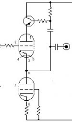
Also way back in this topic/thread, I have done many Lightspeeds Attenuators with buffers after them, solid state and tube, to compensate for low input impedance amps that need a buffer before them, and as stated the "best buffer is no buffer" even (attached) Allen Wrights SLCF (Super Linear Cathode Follower) buffer, which was the best of all the buffers tried, was easily beaten by no buffer at all, this again was confirmed by all my listening testers and myself, it was always better to raise the input impedance of the amps rather than to buffer the Lighspeed Attenuator. I my opinion judging the sound of Lightspeeds, which ever configuration, is a moot point as you are hearing the effects buffer tacked on the end instead of the Lightspeed itself.
Cheers George
This I can say, there has never been a criticism of the sound of the commercial Lightspeed Attenuator MKII or MkI, only praise, with all my customers and with all listening tests done with at least a dozen members of the Sydney Audio Society. At any level over many different systems for the past 5 years. And by myself and many audiophiles over the last 35years that I have been making them.
The only criticism that maybe can be made is that at very low levels there is a need, as in all active preamps to have a loudness switch, but then this is active and negates the advantage of having a totally passive preamp.
Now that's been said, I also want to say that the Mk1 resistor/ldr is not a bad way to build this Lightspeed, in fact is very good still better than any passive or active that it was A/B'ed against, just that the MkII LDR/LDR is better in openness and dynamics.
The Mk1 (resistor/LDR) sounds very good like a good old tube amp (eg Quad II McIntosh 45, and such) just not as tight dynamic or transparent as today's great amps, that is the difference in the MK1 V MKII sound. If you have a system that can tend to be forward or edgy then the MK1 may be the way to go, but then my motto is to fix the source of the problem, not to do a bandaid fix.
Also way back in this topic/thread, I have done many Lightspeeds Attenuators with buffers after them, solid state and tube, to compensate for low input impedance amps that need a buffer before them, and as stated the "best buffer is no buffer" even (attached) Allen Wrights SLCF (Super Linear Cathode Follower) buffer, which was the best of all the buffers tried, was easily beaten by no buffer at all, this again was confirmed by all my listening testers and myself, it was always better to raise the input impedance of the amps rather than to buffer the Lighspeed Attenuator. I my opinion judging the sound of Lightspeeds, which ever configuration, is a moot point as you are hearing the effects buffer tacked on the end instead of the Lightspeed itself.
Cheers George
Attachments
OK, one more:
Adding four parallel resistances can give you an attenuator input impedance that can stay within about 36 Ohms of 7.1k, over the whole range of the pot.
Well, you do have to use a 5.3v supply, for this one. Then just parallel the shunt NLS-32SR2s' LDRs with 21k, and parallel the series LDRs with (ideally) about 15.2086k (e.g. 15k + 210R [or 21k || 62k || 499k, to be exact]).
This one was optimized for a nominal 62k load, where it stays within about 0.5% of 7.1k Ohms, over the entire attenuation range. But, for a 22k load, it still stays within 4.5% of 6.22k Ohms. For a 100k load impedance, it stays within 1.03% of 7.32k Ohms. And for a 1Meg load, it stays within 2.6% of 7.67k Ohms.
Re: Once again.
I have to say that the resistor / LDR combination is indeed less transparent but at present I am only using welwyn RC55's so at present I do not know the full potential of this method - better resistors are coming. It does sound very coherent already.
With my usage I am neither hitting the -100db sweet point of LDR / LDR or the -45db bad point of RES / LDR.
I will try current drive LDR / LDR later
current drive seems to give more powerful, fuller bass
mike
georgehifi said:Now that's been said, I also want to say that the Mk1 resistor/ldr is not a bad way to build this Lightspeed, in fact is very good still better than any passive or active that it was A/B'ed against, just that the MkII LDR/LDR is better in openness and dynamics.
I have to say that the resistor / LDR combination is indeed less transparent but at present I am only using welwyn RC55's so at present I do not know the full potential of this method - better resistors are coming. It does sound very coherent already.
With my usage I am neither hitting the -100db sweet point of LDR / LDR or the -45db bad point of RES / LDR.
I will try current drive LDR / LDR later
current drive seems to give more powerful, fuller bass
mike
- Home
- Source & Line
- Analog Line Level
- Lightspeed Attenuator a new passive preamp