don't bother helping your self then.
Well thanks Andrew for all your encouragement and help with this. We don't all have the same abilities to solve problems and I thought these forums were here to get help when required. Have a nice day!
Thanks Andrew but no thanks
you refused our help.I thought these forums were here to get help when required.
you refused our help.
Andrew, I think you have misunderstood what I was saying. I thanked you for the information that you gave but as I would not be able to perform the task that you suggested I said no thank you. I am not a competent DIY man like many of you on this forum and as the simplest way for me to discover whether a buffer is required is to do what George said is give the LDR preamp a try. If it does not work then I can look to getting a buffer. I was not in anyway rebuffing your suggestion or your help but saying that I am not competant to perform that task.
Hope this clears the issue.
John
Hi Folks
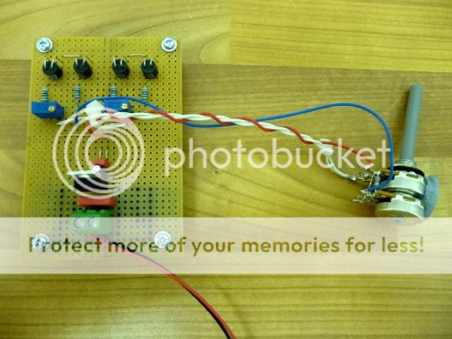
I have recently attempted to put together this attenuator, but I don't appear to have any control over the volume, its permanently set at full!
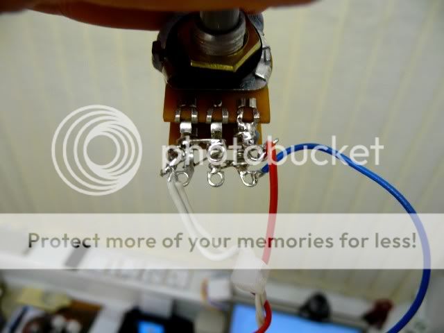
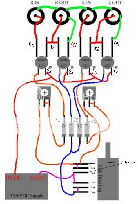
Now that I have recovered from a mild heart attack I have measured the voltage across pins 1 and 3 of the 100k pot. It rises from 0 to 3.5v on a complete turn. When the pot reads 0v the voltage at the 100R shunt resistor is 3.25v. I have soldered a 22R resistor to pin 3 on both channels of the 100k pot.
Here are my readings...
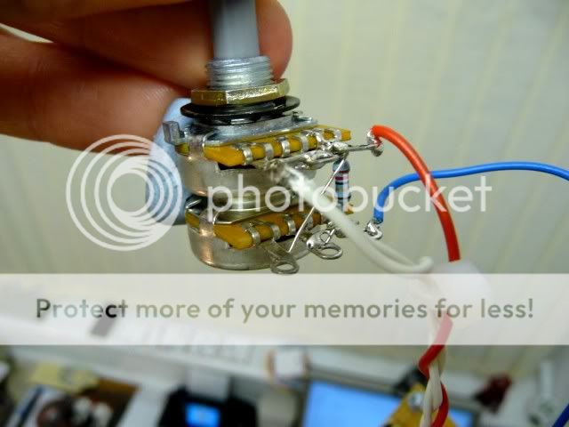
One thing to note is I am using the same SR3 LDR that Puffin has.
I hope this makes sense
Thanks
Richard
I have recently attempted to put together this attenuator, but I don't appear to have any control over the volume, its permanently set at full!
Now that I have recovered from a mild heart attack
I have measured the voltage across pins 1 and 3 of the 100k pot. It rises from 0 to 3.5v on a complete turn. When the pot reads 0v the voltage at the 100R shunt resistor is 3.25v. I have soldered a 22R resistor to pin 3 on both channels of the 100k pot.Here are my readings...
One thing to note is I am using the same SR3 LDR that Puffin has.
I hope this makes sense
Thanks
Richard
Last edited:
It is common for some to think that the white dot on the ldr side is positive, it is not it's negative, check this first, if you have hooked up the white dot to positive I'm afraid you have blown all 4 of the NSL32SR3's
Cheers George
Cheers George
It is common for some to think that the white dot on the ldr side is positive, it is not it's negative, check this first, if you have hooked up the white dot to positive I'm afraid you have blown all 4 of the NSL32SR3's
Cheers George
Hi George
Thanks for your reply.
Sorry I didn't make it very clear. 0v is connected to the dot on the LDR. I have just check continuity between 0v on the power supply and the negative (dot) of the LDR and it beeps.
Richard
Richard - what happens if you turn the pot up full? Does it get quieter?Hi George
Thanks for your reply.
Sorry I didn't make it very clear. 0v is connected to the dot on the LDR. I have just check continuity between 0v on the power supply and the negative (dot) of the LDR and it beeps.
Richard
If so it is the pot that is wired incorrectly.
Richard - what happens if you turn the pot up full? Does it get quieter?
If so it is the pot that is wired incorrectly.
Hi Alan
Nothing happens...it just remains at full volume 🙁
For testing purposes I connected the attenuator to one of my integrated amps. The volume pot on the integrated is set at a moderate level, I thought I could then adjust the lightspeed to see if the volume decreases.
Am I taking the wrong approach?
Thanks
Richard
Does removing the 22R resistor cure the problem?Hi Alan
Nothing happens...it just remains at full volume 🙁
For testing purposes I connected the attenuator to one of my integrated amps. The volume pot on the integrated is set at a moderate level, I thought I could then adjust the lightspeed to see if the volume decreases.
Am I taking the wrong approach?
Thanks
Richard
Alan
There should only be 3 wires involved with the pot. One comes from 5V and goes to the junction of pin 1 of gang X and pin 3 of gang Y and goes to the shunt LDRs.
Then a wire comes from the two pins tied together on gang X and goes to series LDRs and then another wire goes from two pins tied together on gang Y.
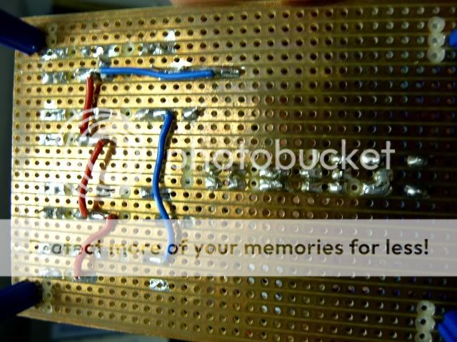
I believe you have GND involved with your pot and that wiring is incorrect.
Also, skip the series resistor til you get it running. If you have a great impedance from the attenuator then no resistor. If you have to low of impedance then use a trimmer in series and go from ~10R to 30~ and see what you like then order that value of resistor and replace the trimmer.
Uriah
Then a wire comes from the two pins tied together on gang X and goes to series LDRs and then another wire goes from two pins tied together on gang Y.
I believe you have GND involved with your pot and that wiring is incorrect.
Also, skip the series resistor til you get it running. If you have a great impedance from the attenuator then no resistor. If you have to low of impedance then use a trimmer in series and go from ~10R to 30~ and see what you like then order that value of resistor and replace the trimmer.
Uriah
Last edited:
Also, placement of your series resistor is incorrect. It should be between 5VDC power supply and the junction of pins 1 and 3 rather than between the pins.
Uriah
Uriah
Thanks Uriah
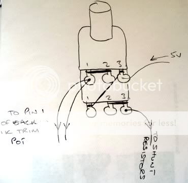
I'll draw a quick sketch of the circuit this evening and post a copy on the forum.
It might be a little bit easier to follow
Richard
I'll draw a quick sketch of the circuit this evening and post a copy on the forum.
It might be a little bit easier to follow
Richard
Try just removing that resistor from the pot.
I see what you did with the pot now and that should work minus the resistor.
Uriah
I see what you did with the pot now and that should work minus the resistor.
Uriah
Try just removing that resistor from the pot.
I see what you did with the pot now and that should work minus the resistor.
Uriah
Hi again
I've removed the resistor, but still no joy.
I'll just check the board again
Also, placement of your series resistor is incorrect. It should be between 5VDC power supply and the junction of pins 1 and 3 rather than between the pins.
Uriah
I have mis-understood where the resistor should be put. It should go between the 5v+ and the 5v connecting point on the pot pins?
If you use a series resistor at all, which can be helpful but is NOT necessary, it should go between your power supply on the positive line and the power input to the pot.
Uriah
Uriah
- Home
- Source & Line
- Analog Line Level
- Lightspeed Attenuator a new passive preamp