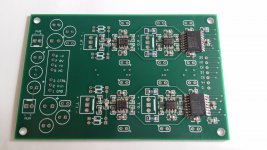
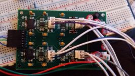
the soldering on the top pic looks attrocious.
Give it a good scrub with a toothbrush and dish washing detergent.
Then look to see which soldered connections are still good and which are shorted and which components fall off.
The lower pic looks a lot better. Shiny joints that appear separate from their neighbours.
Give it a good scrub with a toothbrush and dish washing detergent.
Then look to see which soldered connections are still good and which are shorted and which components fall off.
The lower pic looks a lot better. Shiny joints that appear separate from their neighbours.
A note saying so would have been more helpful !
His first post of the pictures did explain this.
no pics and no explanation.Hi All,
I'm looking for feedback on a first rev PCB design for a PGA2311 volume controller run differentially (i.e: balanced) with OPA1632 as input and output buffers. I don't have a real schematic drawn up as I'm working from the data sheet recommendations. Hopefully I'm providing enough info. I've prototyped the digital side with a though-hole PGA chip and single ended signals.
Here's an album of the PCB layers:
https://goo.gl/photos/3FPrTtyCsy9ceFTo9
- The board will take in a regulated 5vDC supply that will be converted to +/-5vDC using a CUI DC-DC converter that is filtered with caps and radial inductors at the input and outputs. The incoming 5vDC also provide digital power to the PGA chip and can back feed to the uController which is off-board.
- There are 2 circuit grounds but only one ground plane. I split the ground in the lower right corner, the larger portion is for audio ground and the smaller for digital.
- The OPA1632 can take a single ended or differential signal and drive the two inputs of the PGA chip with a differential signal, lowering even-order distortion
- The OPA1632 PCB layouts are based on high-frequency recommendations from the LMP8350 data sheet, including the removal of ground and power planes from beneath the chip and feedback resistors
- The resistors are 0805 package and there are similarly sized caps for PS decoupling close to the pins
- The output connectors are just left of center with 1206 package resistors in series, I'll populate with something around 100 ohm.
- The 2x4 header in the lower right connect to a microcontroller
- The "-" symbols indicate a via to the ground plane. The ground plane is split to isolate the incoming supply voltage and digital.
- The "+" go to the power plane. The power plane is split like the ground plane but part of it is unused, I guess I should ground the unused portion.
Datasheets
http://www.ti.com/lit/ds/symlink/pga2311.pdf
http://www.ti.com/lit/ds/symlink/opa1632.pdf
http://www.cui.com/product/resource/pqmc3-s.pdf
I'm surely leaving something out but I've been looking at this for too long and need some outside opinions.
Brian
He's referring to the post just before the one with embedded pictures. The one you replied to telling me that all forum members can attach pictures. Regardless, I'm glad you think the board with the flowed solder looks good.no pics and no explanation.
Sent from my SM-N900V using Tapatalk
JW tries to screw with my head, or deliberately winds me up. He appears to be succeeding.
I wasn't trying to confuse you. I meant his first attempt to post those two pictures (post 19) had an explanation of the soldering progress.
Last edited:
For the record, since I hate when threads trail off into nothing, I wanted to report back that I pulled this through to the finish line. The forum won't seem to let me embed images so here's some links.
Solder paste and components:
https://goo.gl/photos/RVxTCyqsQsmPao4N7
After flowing, through-holes parts and wiring:
https://goo.gl/photos/3FqAZkBcA1SVKz4m9
Sounds nice, thanks for all the help
Brian
Are the PGA3211s running reliably for you? Another fellow and I have been experimenting with them for a while trying to figure out why some will lock up and/or burn up on volume changes. We seem to have cured it by changing the write speed of the code and moving the pull up resistors on the SPI lines right beside the PGA2311. I'm always interested in other's experience with these.
Last edited:
What kind of a uC are you using? I've built preamps with the PGA2311 controlled by Arduinos and they're running just fine without pullups on the SPI lines.
I'm also using Arduino. As far as I'm aware pullups are needed just like I2C. Possibly you just have better luck than we do because we've had this issue with a few different designs.
That's strange. I've connected all kinds of SPI peripherals to my Arduinos without ever needing pullups. The same goes for I2C. I've found that the internal pullups most of the times are adequate, unless you have very long cables or a particularly noisy environment.
Internal pullups are around 22K in an Atmega328. One or two devices will work fine with I2C if they are near by. If you are using a bunch of devices it usually won't work reliably though. I haven't found a definite reason for the PGA2311 failures but we seem to have them cured with external pullups and altered write timing.
I am also using an Arduino, specifically an Uno. No pull-ups on SPI, never seen anyone do that before. Before getting to this stage I was using a single PGA on a poorly routed bread board and never had an issue once I worked out the correct SPI settings. Maybe I was lucky but none of the reference designs I followed included them either.
One caveat for future users of the PGA series volume controllers: The analog voltage rails must come up before the digital supply. This is not in the datasheet but I was having issues with bleed through of the 5v line to the analog rails... after some reading I found a post on TI's forum where someone on their end confirmed that analog supplies should lead. It might not be an issue with linear supplies but I'm using a little SMPS and the bleed through was screwing with it's ability to reach it's target voltage. On the bread board I added a series resistor and big cap to slow the rise of the digital 5 volts but the PGA's digital side draws so little current that I'm now powering them from an IO pin 500ms after the system powers up.
I can definitely hear an improvement running these in differentially rather than single ended. I'm very happy I went that route.
I am also using an Arduino, specifically an Uno. No pull-ups on SPI, never seen anyone do that before. Before getting to this stage I was using a single PGA on a poorly routed bread board and never had an issue once I worked out the correct SPI settings. Maybe I was lucky but none of the reference designs I followed included them either.
One caveat for future users of the PGA series volume controllers: The analog voltage rails must come up before the digital supply. This is not in the datasheet but I was having issues with bleed through of the 5v line to the analog rails... after some reading I found a post on TI's forum where someone on their end confirmed that analog supplies should lead. It might not be an issue with linear supplies but I'm using a little SMPS and the bleed through was screwing with it's ability to reach it's target voltage. On the bread board I added a series resistor and big cap to slow the rise of the digital 5 volts but the PGA's digital side draws so little current that I'm now powering them from an IO pin 500ms after the system powers up.
I can definitely hear an improvement running these in differentially rather than single ended. I'm very happy I went that route.
A little trick we learned from using Cirrus version is to put a 10uF cap on the digital power and feed it through a 10R resistor. This will delay the digital power up enough to be able to run all from a single supply if desired.
It's interesting some people are having better luck than others with the PGA231x than others. I'm starting to think the code changes we made fixed the issue. My first problem board was one of those EBay red board three input selectors. PGA2311 Stero Remote Volume remote Controller Preamp | eBay I passed it off as a fake IC but the real IC I replaced it with did the same. A few breadboard versions and a preamp I built also went up in smoke. I began working with Linuxworks who did the AMB LCDuino front end. He was experiencing the same issue and we worked together to get it running reliably.
I haven't tried any PGA23xx as a volume control before... Just wondering how does it compare against standard stepped attenuator or relay based attenuator?
They are basically a stepped attenuator with 1/2dB steps. They are very good with proper buffers and layout.
I haven't tried any PGA23xx as a volume control before... Just wondering how does it compare against standard stepped attenuator or relay based attenuator?
I've been using a PGA2310 for years and haven't thought of changing, no reason to.
I haven't tried any PGA23xx as a volume control before... Just wondering how does it compare against standard stepped attenuator or relay based attenuator?
If you don't need remote control, stick with a stepped attnuator or relay based attenuator.
I wouldn't waste my time or money on any PGA23xx design, nor do I understand why anyone else would.
Been there done that. Not only does the sound of those chips blow compared to a inexpensive stepped attenuator from China, then you have to deal with their tendency to "lock up" and shoot the volume to full blast for no apparent reason possible damaging your speakers! Isn't that oh so lovely??🙄
For a remote controlled option, look for a MUSES 72320 design if you want a volume control chip that sounds literally "transparent" and doesn't have all the glitches/problems of the TI PGA23xx series.
Too bad TI doesn't discontinue these chips and replace them with something comparable to the NJR 72320!
I threw my PGA23xx volume control in the trash where it belongs.
- Status
- Not open for further replies.
- Home
- Source & Line
- Analog Line Level
- PGA2311 / OPA1632 Balanced Level Controller

