Hi Salas, I am currently putting my DCG3 together and I got confused abount the orientation of the uPA68H. I figured it out by now (tnx tea) but I stil have a question: looking at the pin-out of the uPA, am I correct in assuming that the orientation is in fact irrelevant, since flipping it means that 1D and 2D are interchanged, same for 1G and 2G and for 1S and 2S, so that only J1 and J2 are swapped? Reason for asking is that, if my assumption is correct, I don't have to desolder and resolder the uPA's, which is never advisable for sensitive components.
Thanks for you support and for yet another awesome design giving me lots of fun in building and finally listening to :=)
Thanks for you support and for yet another awesome design giving me lots of fun in building and finally listening to :=)
Last edited:
Those R3 values fit what batch J3s (marked as Q5s on PCB) the GB organizer has in hand. When showing stronger IDSS median than my original J3 samples, the resulting Id mA tail bias will be little stronger if staying with the 150 Ohm R3 value. It will not make a significant change to the circuit's spec but its all about care for repeatability.
Since the particular J3s & R3s are tested to produce the typically right in-circuit tail current for the input stage just use those resistors provided.
How to test Id and compensate with R3 (useful to who has non pre-selected J3s) is analyzed in post #452 as mentioned and linked from post#1.
Since the particular J3s & R3s are tested to produce the typically right in-circuit tail current for the input stage just use those resistors provided.
How to test Id and compensate with R3 (useful to who has non pre-selected J3s) is analyzed in post #452 as mentioned and linked from post#1.
I have almost finished my build. So here you can see the result.
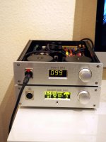
Unfortunately the front came with wrong drilled holes for the headphone jack. I've to check the file I sent them to find out if it's a production fault or my mistake. Maybe I'll take a plate of aluminium and will mount it between jack and frontplate to cover the holes
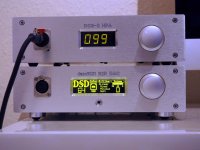
The amp got a ladder volume control with relays and a remote control. I changed the color of the display. Now I will have to dim the display of the DAC to get the same brightness for both devices. the work never ends...
Unfortunately the front came with wrong drilled holes for the headphone jack. I've to check the file I sent them to find out if it's a production fault or my mistake. Maybe I'll take a plate of aluminium and will mount it between jack and frontplate to cover the holes
The amp got a ladder volume control with relays and a remote control. I changed the color of the display. Now I will have to dim the display of the DAC to get the same brightness for both devices. the work never ends...
Attachments
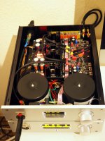
I have almost finished my build. So here you can see the result.
Unfortunately the front came with wrong drilled holes for the headphone jack. I've to check the file I sent them to find out if it's a production fault or my mistake. Maybe I'll take a plate of aluminium and will mount it between jack and frontplate to cover the holes
The amp got a ladder volume control with relays and a remote control. I changed the color of the display. Now I will have to dim the display of the DAC to get the same brightness for both devices. the work never ends...
Maybe this?
SCDP-* - Neutrik
The best thing is to make a new frontplate...
First have to check the where the mistake comes from. I have to ask the shop where I bought the cas if it's possible to get a single frontplate. Otherwise I have to order a complete new case. Last time it was hard to find and I finally bought the last one from a dealer in UK. If I need a new one I have to order in China and wait 1.5 month for the case to arrive.
First have to check the where the mistake comes from. I have to ask the shop where I bought the cas if it's possible to get a single frontplate. Otherwise I have to order a complete new case. Last time it was hard to find and I finally bought the last one from a dealer in UK. If I need a new one I have to order in China and wait 1.5 month for the case to arrive.
That's a good hint...
I simply buy 2 of them and use it for HPA and DAC.
Thanks, that's what I will do
Yeah, white gasket (9) on both machines front sockets to cover the mistake and match looks. Why is there a four pin XLR on the DAM's front by the way? A chips based HPA in bridged configuration lives inside?
No, the dam has onboard balanced output drivers that can drive high impedance headphones directly. I just wired the output to the XLR, rewired my Beyer DT1990 to balanced with a 4pin mini xlr in the left cup.
But you get the best quality from dam by using the "raw"output from the R-2R network and that's single ended to use with an amplifier.
 thoughts of heavily loaded THD test sweeps that may fry it.
 continuous test tones would yield more power
 I did OPA2134 yesterday but had not enough patience to listen carefully, so I swapped back.
I'll take time for this the next days and give a report.
Will it be useful to test lme49990 ? I made good experience using that op with a single to dual adapter in several HPAs and in the dam 1021. For audio its very detailled and nice imo.
You have to buffer power supply voltage with 10µF and 0.1µF MKP direct on the adapter (as mentioned by TI), but then it's fine.
- Home
- Source & Line
- Analog Line Level
- Salas DCG3 preamp (line & headphone)