When "rolling JFET's", changing to 2SK170, are any other changes to the circuit required?
Nothing else, it was tested stable with a variety of input JFET types right from the start.
Example:
Assume 5mA IL is produced by J1 J2, going through two bargraph Leds with 1.8VF each at that current.
So 1.8+1.8=3.6V. If RxJ=390R then 390Ω*0.005Α=1.95V. Add this to the Leds drop. 3.6+1.95=5.55V.
Subtract single Vbe loss in the Sziklai pair. If its 0.6 Vbe then 5.55V-0.6V=4.95V.
Or arrive to nearby goal with same assumptions but three Leds and a small 39R.
VF, IL, Vbe, have significant tolerances they can't be precisely predicted values. But they can be measured in your circuit.
To avoid head scratching and quickly achieve target voltages in symmetry, Rx Ry individual values can be judged with 1k trimmers in their places first (connected in VR rheostat configuration).
Only watch the local power grid variations if any, not to give less than 2.5V DCSTB headroom.
Good point, I have not checked AC from the wall. Ever. In past no need, until now.
Antek has a small 10VA 20V transformer, which in theory should provide an additional 2V overhead and in theory enough current. 10VA / 20V = 500mA, more than the 160mA required.
Or maybe a 24V transformer? In theory an additional 6V of headroom, but still with enough current (10VA / 24V = 416mA).
Because I a using this for headphones, and only headphones, I know that current will always be small. I would prefer to spend $35US on 20V or 24V transformer than $35US on matched 2SK170. I am already very pleased with the sound.
Thoughts?
Keep in mind that with full bridge and capacitor rectification the secondary's AC current spec translates to about 40% less DC current capability.*
DCG3 pulls steadily the 160mA you set because it works in Class A. That much should cover all modes and practical loads you may ask it to cater for.
Very seldom to get peak demand over that much standing current bias. Say if you push low impedance & low sensitivity headphones to very high levels. Some weird planars maybe.
Any Tx has to be calculated to do two things:
A. Meet the load's steady & peak current consumption without falling lower than its nominal secondary AC voltage.
B. Not getting too hot itself while doing that. Meaning to allow power headroom when choosing Tx spec for a config.
Given your practical experience with those 10VA Anteks, if already meeting the above criteria at 18V AC spec they shall do the same at 20V AC spec. Still, if your 3V headroom isn't challenged by grid variations there's not much else than +2V to gain with new same small size trafos. Their output impedance will remain about the same.
If curious about the local grid's impact on headroom you can leave the DMM measuring the preamp's raw DC for a day or two with the min/max button engaged. Or sample for a week in day's hours you are likely to listen. Then decide. Nothing to lose except you may need a new set of meter batteries.")
*Design Guide For Rectifier Use - Hammond Mfg.
DCG3 pulls steadily the 160mA you set because it works in Class A. That much should cover all modes and practical loads you may ask it to cater for.
Very seldom to get peak demand over that much standing current bias. Say if you push low impedance & low sensitivity headphones to very high levels. Some weird planars maybe.
Any Tx has to be calculated to do two things:
A. Meet the load's steady & peak current consumption without falling lower than its nominal secondary AC voltage.
B. Not getting too hot itself while doing that. Meaning to allow power headroom when choosing Tx spec for a config.
Given your practical experience with those 10VA Anteks, if already meeting the above criteria at 18V AC spec they shall do the same at 20V AC spec. Still, if your 3V headroom isn't challenged by grid variations there's not much else than +2V to gain with new same small size trafos. Their output impedance will remain about the same.
If curious about the local grid's impact on headroom you can leave the DMM measuring the preamp's raw DC for a day or two with the min/max button engaged. Or sample for a week in day's hours you are likely to listen. Then decide. Nothing to lose except you may need a new set of meter batteries.
*Design Guide For Rectifier Use - Hammond Mfg.
Keep in mind that with full bridge and capacitor rectification the secondary's AC current spec translates to about 40% less DC current capability.
I have seen that page before, and others, but have not been able to match theory with practice. Theory says that at full current VDC = VAC * 0.45, but to date I've not seen anything close. In practice, at less than full current, the small 10VA xfmr produces DVC = 1.1X ACV, which is not anywhere close to 0.45X. A very big difference. But this is my problem, not yours.
If curious about the local grid's impact on headroom you can leave the DMM measuring the preamp's raw DC for a day or two with the min/max button engaged.
An excellent idea, thank you. I do not use min/max button often, now I can put to good use.
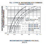
0.45xVac is for single or double diode rectification direct to a resistor load. Our case is "full wave bridge capacitor input load" its the right hand column's third schematic. Factor in diode VF losses for VDC Peak. Tx winding resistance and core losses also. DCTB's BOM lists SB180 (Schottky).
Attachments
5 years anniversary
Near my former DCG2 (today now DCG3) it's been 5 years of steady preamp Salas...
Congrats for that!
I took it out, for rebuilding into another chassis giving it 1K for the R6's (gain) now.
Checking bias, dc-offset (without opamp) and then with opamp, telling me that it did not change at all during the years
Gain going nicely from 2x to 3x now...
Will you provide a new build soon? ... Nevermind i will keep this Salas... 
Jesper.
Near my former DCG2 (today now DCG3) it's been 5 years of steady preamp Salas...
Congrats for that!
I took it out, for rebuilding into another chassis giving it 1K for the R6's (gain) now.
Checking bias, dc-offset (without opamp) and then with opamp, telling me that it did not change at all during the years
Gain going nicely from 2x to 3x now...
Will you provide a new build soon? ... Nevermind i will keep this Salas...
Jesper.
Attachments
it's been 5 years of steady preamp Salas...
...Will you provide a new build soon? ... Nevermind i will keep this Salas...
Jesper.
Happy anniversary Jesper
Finally!
Hello Salas,
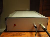
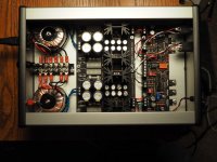
It's finally done!
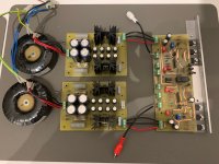
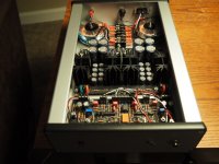
Now you see why I wanted to use smaller 10VA xfmrs, they are a nice fit in this particular chassis, larger and there would be little to no space for A/C. No volume control, I control that with the Fiio player. Power switch on the back to keep AC separated from audio.
I can't say enough how much I like this amp. The combination of player, amp and headphones are very musical, very lifelike, to my ears.
One last and final question: how, or where where, did you find the uPA68AH? I think it is responsible for such great sound.
Hello Salas,
It's finally done!
Now you see why I wanted to use smaller 10VA xfmrs, they are a nice fit in this particular chassis, larger and there would be little to no space for A/C. No volume control, I control that with the Fiio player. Power switch on the back to keep AC separated from audio.
I can't say enough how much I like this amp. The combination of player, amp and headphones are very musical, very lifelike, to my ears.
One last and final question: how, or where where, did you find the uPA68AH? I think it is responsible for such great sound.
Attachments
Congratulations
Very nice compact build. Max bandwidth at all levels when without a vol pot too. Keep it as is since it has great synergy with the rest of your gear.
When I got those five I verified they had excellent inter-pair curves matching and a high enough (2SK117 like) transconductance.
A year passed and I heard a friend talking about his six meters long interconnects to his biamped speakers system. One pair to his main speakers amp and another pair to his subwoofers amp. So I thought that's quite a lot of cables capacitance to drive from a common output. The very popular DCB1 unity gain small JFETs buffer did not have the standing current to properly support that. My 6V6 triode configured 20mA biased tube preamp design was already better sounding in his system. Despite its higher output impedance.
It dawned on me why not design a strong solid state preamp with power MOSFETs output to remedy that, plus having some gain for a phono source.
I decided an all FET few as possible active components and throughout DC coupled policy. But also not to base it on some overpriced too scarce input monolithic pair. To be easier repeatable. There it was the opportunity to employ the cheap & cheerful (back then at least) uPAs. It was bugging me a bit they were sitting in a parts bin not utilized in something useful yet.
So I went on and made many experiments measuring and listening to various circuit building blocks in various working together schemes and then all over again.
No simulations yet, only breadboarding and measuring, those I run after the bench tests as a method to keep the iterations on file.
I arrived to what you got as DCG3 after about two months of everyday few hours work. I tried to have an output stage that actually gains stability with cables capacitance. Not a follower (buffer). Was measuring good enough for its simplicity as well. Since the bias current was plenty, I gave it an additional output route for monitoring with headphones too.
I didn't survey other same purpose circuits at all so to avoid subconscious gravitation towards any particular designer's examples of ingenuity or subjective quality comments about. Possible resemblance to similar electronics art is only a coincidence.
I asked a couple of friends if they would also like to build it and give me feedback. One in Greece one in Asia. Without giving them any performance clues. Only a schematic and technical instructions when asked, they had to make it on perfboards of their own. Avid DIY builders, they had tried many known preamp circuits in the past.
They said it was very nice. Furthermore I noticed they adopted it in their systems. Then I instructed pcbs, constructed and tried them, all was good. After that I published the completed design and measurements for all of you guys.
That's the short story of DCG3's inception, design, and the role of uPA68H's in it. It was not a lab perfect amp design goal, but I hoped technically decent enough for its simplicity, reliable, repeatable, steady, and with a sound signature that I found adequate.
After five years it was first published I am happy to see it made it to a good number of fellow builders Hi-Fi racks too. Thanks.
Very nice compact build. Max bandwidth at all levels when without a vol pot too. Keep it as is since it has great synergy with the rest of your gear.
About the uPA68H, I had five pieces because I saw them on some eBay listing. Could prove fake but they were listed cheap considering their also being good old Japanese duals as the usually sought-after Toshiba. Nobody actively used this NEC monolithic. Never saw it used in DIY Audio at least. Maybe useful for the odd vintage gear repair, not sure. Even a complete uPA68H datasheet was difficult to locate. I thought alright, why not sample it.One last and final question: how, or where, did you find the uPA68AH?
When I got those five I verified they had excellent inter-pair curves matching and a high enough (2SK117 like) transconductance.
A year passed and I heard a friend talking about his six meters long interconnects to his biamped speakers system. One pair to his main speakers amp and another pair to his subwoofers amp. So I thought that's quite a lot of cables capacitance to drive from a common output. The very popular DCB1 unity gain small JFETs buffer did not have the standing current to properly support that. My 6V6 triode configured 20mA biased tube preamp design was already better sounding in his system. Despite its higher output impedance.
It dawned on me why not design a strong solid state preamp with power MOSFETs output to remedy that, plus having some gain for a phono source.
I decided an all FET few as possible active components and throughout DC coupled policy. But also not to base it on some overpriced too scarce input monolithic pair. To be easier repeatable. There it was the opportunity to employ the cheap & cheerful (back then at least) uPAs. It was bugging me a bit they were sitting in a parts bin not utilized in something useful yet.
So I went on and made many experiments measuring and listening to various circuit building blocks in various working together schemes and then all over again.
No simulations yet, only breadboarding and measuring, those I run after the bench tests as a method to keep the iterations on file.
I arrived to what you got as DCG3 after about two months of everyday few hours work. I tried to have an output stage that actually gains stability with cables capacitance. Not a follower (buffer). Was measuring good enough for its simplicity as well. Since the bias current was plenty, I gave it an additional output route for monitoring with headphones too.
I didn't survey other same purpose circuits at all so to avoid subconscious gravitation towards any particular designer's examples of ingenuity or subjective quality comments about. Possible resemblance to similar electronics art is only a coincidence.
I asked a couple of friends if they would also like to build it and give me feedback. One in Greece one in Asia. Without giving them any performance clues. Only a schematic and technical instructions when asked, they had to make it on perfboards of their own. Avid DIY builders, they had tried many known preamp circuits in the past.
They said it was very nice. Furthermore I noticed they adopted it in their systems. Then I instructed pcbs, constructed and tried them, all was good. After that I published the completed design and measurements for all of you guys.
That's the short story of DCG3's inception, design, and the role of uPA68H's in it. It was not a lab perfect amp design goal, but I hoped technically decent enough for its simplicity, reliable, repeatable, steady, and with a sound signature that I found adequate.
After five years it was first published I am happy to see it made it to a good number of fellow builders Hi-Fi racks too. Thanks.
- Home
- Source & Line
- Analog Line Level
- Salas DCG3 preamp (line & headphone)