Yes, you are right, but Microcap 9.0 has very limited library of MOSFET transistors, which can be purchased now. And additionally, half of models are unstable in exotic schemes in MC9. Therefore this version contain BF998+BSS84 which is simply the most stable with MicroCap 9.0.BF998 is a discontinued RF dual-gate n-channel mosfet with Vds(max) of 12V only, limiting it to +/- 6V rails. For practical audio applications, commodity 2N7002 is likely to be more useful at rails of +/- 15V and higher.
Thank you for suggestion 2N7002, but I think the best will be pairs of power MOSFET IRF510+IRF9150, or recent "fashion" lines of so-called "linear power MOSFETS", such as discontinued BUK9535-55A or newer models by several MOSFET manufacturers.
This is a pretty old approach - to use power mosfets on input - for example Ayre V3.
Ayre Acoustics V-3 power amplifier | Stereophile.com
Power mosfets have THICK wires inside them, like tubes. This is the key point, I think.
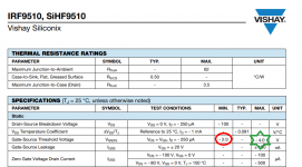
Discrete OpAmp on N+P channel RF MOSFETs: IRF510+IRF9510
Upd:
This schematic (above) is very stable and robust. It can work with almost ANY complementary pairs, or close-to-complementary.
This minimalistic design follows the early classic OpAmp design with low count of stages.
This makes it auto-balanced (with only 2 tuning resistors 1.4k and 14 Ohm), and robust to discrepancy in transistors specs.
Now with power voltage = 35V+35V
Discrete OpAmp on N+P channel (general power) MOSFETs: IRF510+IRF9510.
Software model only. Made with MicroCap 9.0.
Spec:
Open loop gain ~ 60dB.
Bandwidth limit at Gain=1~ 23 MHz.
THD at gain=60dB ~0.013% at 8V output.
THD at gain=40 dB ~0.0001% at 1V output.
Schematic:
Currents:
Freq-Phase at gain=60dB:
Freq-Phase at gain=40dB:
THD at gain=60 dB:
THD at gain=40dB:
Last edited:
In the top schematic of post #3342, X2 and X5 do not have source degeneration resistors. Why not? Same for X3 and X4.
If the transistor in position X2 is the Red Device, while the transistor in position X5 is the Green Device, your opamp will have enormous input offset voltage.
_
If the transistor in position X2 is the Red Device, while the transistor in position X5 is the Green Device, your opamp will have enormous input offset voltage.
_
Attachments
Yeap, you are right. I have just quickly substituted the IRF510 transistors to the first circuit (BF998) this morning and tuned the current to lowest THD. There should be resistors in the sorces for various models of transistors.In the top schematic of post #3342, X2 and X5 do not have source degeneration resistors. Why not? Same for X3 and X4.
If the transistor in position X2 is the Red Device, while the transistor in position X5 is the Green Device, your opamp will have enormous input offset voltage.
_
Thanks.
post #3342: Useless schematics.
_Simulation only is far from realities....Simulated transistors are identical. A decent op amp design should deal with transistor mismatch and specify Vos, Ios, Ibias.
_60 dB gain.....Is no use as an operational amplifier. A decent op amp should have at least 100dB gain.
_Simulation only is far from realities....Simulated transistors are identical. A decent op amp design should deal with transistor mismatch and specify Vos, Ios, Ibias.
_60 dB gain.....Is no use as an operational amplifier. A decent op amp should have at least 100dB gain.
100 dB gain requires ONE EXTRA STAGE, which is not good for sound.post #3342: Useless schematics.
_60 dB gain.....Is no use as an operational amplifier. A decent op amp should have at least 100dB gain.
100 dB gain requires ONE EXTRA STAGE, which is not good for sound.
That's your opinion, so label it as such. My opinion is add stages until no useful further improvement can be got. Adding stages can and does improve performance in an opamp, such as more open loop gain, more current handling, improved open loop linearity (by reducing input signal amplitude). This is the opinion of most engineers!
The "most engineers" have been misled for many years. The result - dead dry sound of modern music.That's your opinion, so label it as such. My opinion is add stages until no useful further improvement can be got. Adding stages can and does improve performance in an opamp, such as more open loop gain, more current handling, improved open loop linearity (by reducing input signal amplitude). This is the opinion of most engineers!
Design for 100dB gain has no logic - there is no audio device requiring 100dB gain. There no logical reason for huge gain, unless you want deep negative feedback in order to reduce THD distortions.
But deep negative feedback SPREADS the harmonics and is increasing their ORDER, thus is adding great mess to music. Unfortunatelly, this was greatly stressed and detailed only in old books on (tube) electronics (as early as 1936), but in modern books it is described only briefly.
Add here skin-effect distortions in passive resistive circuit of negative feedback, lower resistance of this circuit in transistor amplifiers, and here the result - death of modern music as to sound quality comparing the tube ages.
The "most engineers" have been misled for many years. The result - dead dry sound of modern music.
In my experience the 'dry, dead sound' of modern electronics (not music) is down to inadequate power supplies when using classAB electronics. Nothing much to do with feedback at all. I'm listening right now to an AD815 headphone amp where the device has something like 3Mohm typical transresistance. The 'dry, dead sound' is avoided by using enough caps on the rails ergo it can't be due to too much feedback.
Too little feedback is what 'spreads the harmonics', not too much.
Headphones Ampifier with tube sound on TL071
Here the schematic of simplest headphones ampifier with tube sound on TL071 OpAmp.
The difference - the VERY HIGH resistance of negative feedback. It is made by CAPACITORS instead of resistors. Therefore the AC current (and parazitic skin-effect) in feedback circuit IS VERY LOW.
Resisror R3 is needed for balancing DC offset. It is 10 Giga-Ohm (I used R in a glass cage).
This approach very simple : the lower the currents - the lower skin-effect. To reduce currents use high-impedance circuitry.
This is in what tube amplifiers differ from transisitors.
If You are an engineer - you will spend only 20-30 min on maketing this simples schematic and check the sound. Try.

This is not my invention - you can find capacitive feedback in design of high-impedance photodiodes sensors apmlifiers, in piezo-sensors amplifiers atc.
But nobody used it for audio.
Important note: in order to obtain really clean tube sound the power supply should contain LC filter immediatelly after rectifier with huge incuctor of 10 Henry. You can simply use coil of another transformer instead real inductor, because the current is 2....20 mA or so. I also used then precise LM317 LDOs - two in a row for each rail.
The clean power supply is crucial.
Really?The "most engineers" can tell you that you do not understand feedback, you do not understand operational amplifiers techniques.
Here the schematic of simplest headphones ampifier with tube sound on TL071 OpAmp.
The difference - the VERY HIGH resistance of negative feedback. It is made by CAPACITORS instead of resistors. Therefore the AC current (and parazitic skin-effect) in feedback circuit IS VERY LOW.
Resisror R3 is needed for balancing DC offset. It is 10 Giga-Ohm (I used R in a glass cage).
This approach very simple : the lower the currents - the lower skin-effect. To reduce currents use high-impedance circuitry.
This is in what tube amplifiers differ from transisitors.
If You are an engineer - you will spend only 20-30 min on maketing this simples schematic and check the sound. Try.
This is not my invention - you can find capacitive feedback in design of high-impedance photodiodes sensors apmlifiers, in piezo-sensors amplifiers atc.
But nobody used it for audio.
Important note: in order to obtain really clean tube sound the power supply should contain LC filter immediatelly after rectifier with huge incuctor of 10 Henry. You can simply use coil of another transformer instead real inductor, because the current is 2....20 mA or so. I also used then precise LM317 LDOs - two in a row for each rail.
The clean power supply is crucial.
Last edited:
I agree that TL071 can sound very good but notice your circuit does not get rid of the large gain of the TL071, >100dB for frequencies below around 40Hz.
What gives the good sound is that the TL071 is very lightly loaded - this can be achieved with high value resistors too, given the JFET input stage. The limitation of the circuit you've shown is the 100k load resistor (after the 10uF cap) - I suggest increasing that and see if you like the sound more.
What gives the good sound is that the TL071 is very lightly loaded - this can be achieved with high value resistors too, given the JFET input stage. The limitation of the circuit you've shown is the 100k load resistor (after the 10uF cap) - I suggest increasing that and see if you like the sound more.
As about power supply - totally agree.In my experience the 'dry, dead sound' of modern electronics (not music) is down to inadequate power supplies when using classAB electronics....
See above about LC filter and precise LDOs. Transistors amplifiers sound is VERY sensitive to power supply. This is not about PSRR, this is about drops in voltage/current to zero in rectifiers. It is not possible to eliminate it without inductors, the bigger, the better.
Simplest calculation shows up that energy in power supply capacitors of tube amplifiers - due to higher voltage (energy ~ V^2....) - is 20-100 times higher than in transistor amplifiers (much lower voltage).
If used as a preamp - yes, agree.I agree that TL071 can sound very good but notice your circuit does not get rid of the large gain of the TL071, >100dB for frequencies below around 40Hz.
What gives the good sound is that the TL071 is very lightly loaded - this can be achieved with high value resistors too, given the JFET input stage. The limitation of the circuit you've shown is the 100k load resistor (after the 10uF cap) - I suggest increasing that and see if you like the sound more.
But there will be 100 Ohm headphones there. This is an example for 100-200 Ohm headphones. If use 30... 50 Ohm headphones there will be audible distortions due to TL071's AB class output stage - as You already said here. But the sound will be crisp clean tube manner anyway.
I've not myself had good results feeding TL071 into such low impedance loads. 10uF is rather too low a value cap to get decent bass into 100ohms but the real limitation will be that the opamp itself has a couple of large-ish resistors at its output (internally 64ohm and 128ohm) if you check the internal schematic.
On chokes in series with power supplies - agree, I pretty much always use them. Multiple ones if the power comes from a mains transformer.
On chokes in series with power supplies - agree, I pretty much always use them. Multiple ones if the power comes from a mains transformer.
Last edited:
O-o-ps, sorry, you are absolutely right, the capacitor should be about 10000 uF, for sure. This schematic was quickly taken from the bigger one.I've not myself had good results feeding TL071 into such low impedance loads. 10uF is rather too low a value cap to get decent bass into 100ohms but the real limitation will be that the opamp itself has a couple of large-ish resistors at its output (internally 64ohm and 128ohm) if you check the internal schematic.
Thanks.
Corrected version with 10000uF output capacitor:

Update: what I wanted to say by this schematic is - even the old, cheapest TL071 Jfet-BJT OpAmp can sound like the tube.
"Like the tube" does not mean here "with nice second order harmonics as some tubes" but "crisp clean like tube, alive, with no transistor mess and compression".
Last edited:
With those values the noise will be quite high. In a sense it will be tube like. . .
The jfets in a tl071 will have enough leakage/bias current that the gigohm resistor will generate substantial voltage. It will also change a lot as the chip warms up.
The "skin effect" thing with resistors makes no sense. There are voltage effects and frequency effects that are real and best managed with thin film low value resistors.
The harmonic multiplication issue shows up when you do not have enough loop gain. There are many amps on Diyaudio that have lots of loop gain and really low distortion.
Datasheet shows up input resistance of 10^12 Ohm, 1000 GOhm, 1TOhm. The versions of TL071 may vary. I used TL071CP - the best in sound. There was no problem with 1 GOhm resistor, with feeding signal to either + or - input. The sound with signal on (-) input was slightly (very slightly, took a long time to decide) better than (+).With those values the noise will be quite high. In a sense it will be tube like. . .
The jfets in a tl071 will have enough leakage/bias current that the gigohm resistor will generate substantial voltage. It will also change a lot as the chip warms up.
But for example for phono preamp with RIAA corretion you have to use (-) for feedback and (+) inputs for signal path, in order to avoid side effects.
The sound with 10 GOhm was better (not too much) than 1 GOhm.
For the stability purposes Ok, please, use 1 GOhm.
Use mica capacitors for feedback circuit at best, then ceramic, then various poly*** - as usual in RF devices.
P.S. (-) inverting; (+) non-inverting.
Dear Alex.
Demian is right about the impedance's. 1G Ohm or more has higher resistance than dust in normal humidity. Even if the process of design a PCB board, resistance in that order would require GND guards.
Up two a few megaohm is okay. Noise would be an big issue. Not noise from the jfet but thermal noise from the resistor it self.
Distortion due to voltage modulated capacitance on the input of the JFET would be the next concern.
BR
Sonny
- Home
- Source & Line
- Analog Line Level
- Discrete Opamp Open Design