I have a circuit with 2 TL074 quad op amps. I'm using 1 of the Amps on the first TL074 as a rail splitter for the other 3 on the same TL074. I need a rail splitter for 3 of the amps on the 2nd TL074. My question is, can I use the one rail splitter, of do I need to use 2 separate splitters? The forth amp on the 2nd TL074 is already being used but doesn't need the half voltage. If I can, what is the best values to use for the splitter's resistors and capacitor?
Thanks for any help.
Thanks for any help.
You might consider using this virtual ground circuit for the best results:
A Regulated Virtual Ground Circuit
A Regulated Virtual Ground Circuit
Don't want to hijack but this might be a simpler solution with fewer parts count. What do you guys think of this one?
Craig's Split Supply
Craig's Split Supply
I have used that sort of approach before, but with an L165 (3a power opamp). It worked, somewhat, but needed a 100ma + constant current load on it to sound any good. See the L165 datasheet here: http://octopart.com/partsearch#search/requestData&q=l165 On page 6 of the datasheet you will find a circuit for "split supply". The Goldpoint Regulated Virtual Ground really sounds best - by far - in my application. A Regulated Virtual Ground Circuit BTW, you could probably use an LD1085V12 (reducing parts count by 5 parts) instead of the LD1085V shown, if +/- 6V is adequate for your application...
In the interest of reducing parts count by not using an adjustable regulator such as an LD1085V, but instead using a fixed value 12V regulator:
1) If we cannot get the LD1085V12 (12V, 3A) anymore, try the LM338T (12V, 5A) .
2) There may be some other suitable 12V, 1A - 5A fixed value regulators out there. On this I would like to hear from others... If your application is low enough current you can use a L7812CT, an MC7812, or something similar...
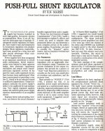
I put the "Push-Pull Shunt Regulator" (Audio Amateur, 1/88, pp. 26-29) circuit schematic into LTSPICE, and ran some simulations. To my surprise, the circuit appears not to regulate at all; output voltage was displaced from the midrail point by approximately eleven volts (!). I've studied the schematic for quite a long time, and I confess that I cannot find any trace of a negative feedback mechanism which (a) detects when the output is non-midrail, and then (b) pulls it in the other direction (towards the exact midpoint between the rails). Indeed there isn't a single node anywhere in the circuit, whose voltage is at the exact midpoint between the rails.
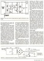
Maybe this is merely a drafting error; perhaps R2 and R3 were intended to connect to the upper rail and lower rail, respectively. If so then their junction would have been a midrail reference point, and the opamp's feedback loop would have stabilized the output at the midrail point. However the accompanying PCB design matches the schematic shown here, with R2 and R3 not connected to the rails. The previous design from 5 years before, shown in Figure 2 of the TAA article, did connect these resistors to the rails. Hmmm.
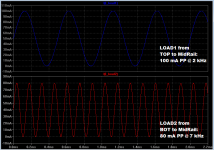
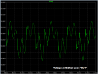
In simulation I loaded the regulator with a 0-to-100mA sinewave at 2 kHz, from Top to Midrail; and with a 0-to-80mA sinewave at 7 kHz, from Midrail to Bot. I've attached a 2-panel plot of these currents, below. The "regulated" voltage at the output is shown in a second plot. Its amplitude is ~ 60 millivolts peak to peak, implying an output impedance of about 0.6 ohms. There is also a bit of oscillatory ringing at approx 72 kHz, which dies away after two or 3 cycles. Most importantly of all, the output voltage is displaced about 10.9 volts above the midrail point.
Maybe this is merely a drafting error; perhaps R2 and R3 were intended to connect to the upper rail and lower rail, respectively. If so then their junction would have been a midrail reference point, and the opamp's feedback loop would have stabilized the output at the midrail point. However the accompanying PCB design matches the schematic shown here, with R2 and R3 not connected to the rails. The previous design from 5 years before, shown in Figure 2 of the TAA article, did connect these resistors to the rails. Hmmm.
In simulation I loaded the regulator with a 0-to-100mA sinewave at 2 kHz, from Top to Midrail; and with a 0-to-80mA sinewave at 7 kHz, from Midrail to Bot. I've attached a 2-panel plot of these currents, below. The "regulated" voltage at the output is shown in a second plot. Its amplitude is ~ 60 millivolts peak to peak, implying an output impedance of about 0.6 ohms. There is also a bit of oscillatory ringing at approx 72 kHz, which dies away after two or 3 cycles. Most importantly of all, the output voltage is displaced about 10.9 volts above the midrail point.
Attachments

not much chance if you bootstrap everything - really have to have a "external" reference V somewhere in the system - like a R divider from the the rails you're trying to split
bootstrapping an op amp's supply pins has unobvious stability consequence - and common Spice models don't get either gain reference or ps pin currents right
nor is 5534 unity gain stable
bootstrapping an op amp's supply pins has unobvious stability consequence - and common Spice models don't get either gain reference or ps pin currents right
nor is 5534 unity gain stable
Last edited:
Another point besides moving location of R's is your input is done wrong. Input must be floating -- not grounded. Like a 50v power source for +/- 24vdc output... ungrounded as explained in the article.
[Afterwards, try adding some series R or a series regulated input-floating... sim what happens.]
Thx-RNmarsh
[Afterwards, try adding some series R or a series regulated input-floating... sim what happens.]
Thx-RNmarsh
Last edited:
As shown it was a rail splitter but with the R's changed to rails it regulates as well. That didnt get shown and was an oversight in writing/editing.
Thanks for doing a SIM on it and when it is working, it can be optimized. But I still want to get up here the article. There were no sim software at the time of developing concepts and it was very much a DIY thing. No computers either (except a Commodore and other toy compuetrs in their infancy). The derivation of the concepts is useful to others for expansion - though a lot of that has occured already by others who have taken the ball and run with it since then.
Thx-RNMarsh
Last edited:
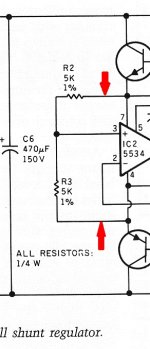
The original article had R2 and R3 incorrectly connected, in the same way I've shown; a snippet of the original schematic is below. The PCB layout faithfully duplicated the error, too.
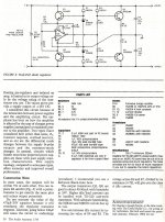
I just found out that a guy named John Adelsbach noticed this same problem in 1988, and published a corrected circuit in TAA 4/88 (pp. 46-47). He concluded the input resistors were wrong in the original article. At the end of his article, an italicized passage appears: Mr. Marsh comments: The 5k resistors should go to rails as J. Adelsbach has indicated. ...
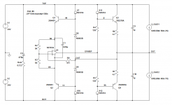
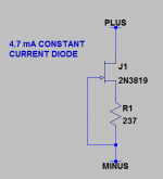
It doesn't take long to put together a simulation of the (incorrect) original rail splitter circuit, or to make modifications & test them out. Try it yourself, you'll enjoy it! The only slightly unusual element in this circuit is the 4.7 mA constant current diode 1N5314. I modeled it the easy way, using the primitive elements already present in LTSPICE: a JFET and a resistor. Voila, a 4.7 mA constant current diode with its own schematic symbol. Simulated Zout at 4.7 mA was half a megohm; plenty good enough.
I just found out that a guy named John Adelsbach noticed this same problem in 1988, and published a corrected circuit in TAA 4/88 (pp. 46-47). He concluded the input resistors were wrong in the original article. At the end of his article, an italicized passage appears: Mr. Marsh comments: The 5k resistors should go to rails as J. Adelsbach has indicated. ...
It doesn't take long to put together a simulation of the (incorrect) original rail splitter circuit, or to make modifications & test them out. Try it yourself, you'll enjoy it! The only slightly unusual element in this circuit is the 4.7 mA constant current diode 1N5314. I modeled it the easy way, using the primitive elements already present in LTSPICE: a JFET and a resistor. Voila, a 4.7 mA constant current diode with its own schematic symbol. Simulated Zout at 4.7 mA was half a megohm; plenty good enough.
Attachments
It works even better with a 3-term pre-reg in series as a source to the push-pull shunt reg. As I indicated in the article, I had also tried the idea on 1/2 of a stereo amp to power the other half. Worked great for power amps as well!
Thx-RNMarsh
Every 25 years or so it's best to go back over the basics and sometimes the origins of what becomes mainstream.... for newbees and refreshers for the old geezers:
Note Fig2 is the correct form to use re. R1,2 for R2,3..
Enjoy!
Attachments
Last edited:
- Status
- This old topic is closed. If you want to reopen this topic, contact a moderator using the "Report Post" button.
- Home
- Source & Line
- Analog Line Level
- Op Amp Rail Splitter Question