Actually, if you look at my disco mixer link, I wound my own Power supply chokes out of surplus toroids from a trash PCAT power supply. Twenty turns. Stops hash from the lamp dimmer when I turn it on. I moved my power supply out of the mixer box, use a 18 VDC wall transformer now (from a slot car set). Reduced hum, no switching noise. Bill's op amp circuit is a little primitive, use the schematic from your unit or a Peavey XR1200 schematic or something but use DIP8's so you can swap them out without soldering. I'm using phosphor bronze tyco sockets, no connection problems yet. The PCB from MCMelec would be useful for op amp circuits but you need a ferous steel box (magnet sticks to it) to keep out RF hash from computers etc. Cheap disco mixers have single sided PCB's and a steel box, that is why I suggested one as a test mule. The faster the chip, the closer the PS bypass caps (disc ceramic) need to be. Mine are on the back of the IC socket.
Last edited:
For some reason, after sleeping on it, I'm finding the idea more intriguing, especially since someone else is taking the risk.
So... what if you first reverse engineered the schematic to figure out where you can swap in your own opamp circuits? This way, you're literally bypassing the specific opamp circuits you want to upgrade and you're not dealing with the effect of the board's resistors and caps on your choice of opamp.
I guess, that's really just making your own mixer and using the board's pots and tone controls for it. And now that I think of it, that's probably why there are still 5532's... for tone control. It's easy enough to redesign a buffer circuit using new opamps, but I'm guessing that the flavour and response of tone controls can be really dependent on component choices.
") ensen.
ensen.
So... what if you first reverse engineered the schematic to figure out where you can swap in your own opamp circuits? This way, you're literally bypassing the specific opamp circuits you want to upgrade and you're not dealing with the effect of the board's resistors and caps on your choice of opamp.
I guess, that's really just making your own mixer and using the board's pots and tone controls for it. And now that I think of it, that's probably why there are still 5532's... for tone control. It's easy enough to redesign a buffer circuit using new opamps, but I'm guessing that the flavour and response of tone controls can be really dependent on component choices.
ensen.BTW, Douglas Self is also very impressed with the LM4562 and compares it against the NE5532 in his book Small Signal Design. Seemingly (from memory) his single objection is that it costs 10x what the NE5532 costs. But today you can get a single LM4562 for $3 (at D-K).
As for removing either an 8-DIP or SOIC, I just carefully snip the legs and toss the old op amp. No heat to damage the pcb...
As for removing either an 8-DIP or SOIC, I just carefully snip the legs and toss the old op amp. No heat to damage the pcb...
Considering all that has been said, there is a huge risk in this project. I am a novice at all this mod stuff. I built a few projects b4, but mainly by following someone else's part list and schematics. I am great at soldering and following simpler schematics. That's why I thought it would be easy enough to just change an opamp or something.
The Analog Devices AD744 (single) and AD746 (dual) will outperform any of the TI parts you are considering. I have performed extensive testing on all these parts and the AD744/AD746 measure better distortion AND SOUND BETTER, i.e. better high-frequency clarity. The OPA2134(dual), OPA2604 (dual) sound rather nasty. The ultimate solution is OPA627, but it is not available in dual pkg. There are adapter boards that let you mount 2 singles into a dual DIP8 socket. Check eBay, they aren't very expensive.
If you can solder and are confident of removing the SMD devices (did you read my link post #23) then I wouldn't hesitate. Using something like the OPA2604 or LM4562 and there will be no problem. It's a straight swap.
I'm just reading TomHintons post re the "nasty sounding" OPA2604 as I'm typing this That's not my experience but I do accept that sound is a very personal thing.
I'm just reading TomHintons post re the "nasty sounding" OPA2604 as I'm typing this
That's not my experience but I do accept that sound is a very personal thing.The AD744/AD746 have sound character most nearly like OPA627. Have you ever experimented with these AD parts?
No.
If you've never swapped opamps before, then try this instead. Build an input 1:1 buffer with a dip socket then insert it between the mixer and it's main buss. That way you should have the main slider for volume and little or no circuitry between the monitors and the buffer. Now start swapping opamps and include the 5532 and 4582's that are in the mixer. That should give you a very good indication of what the sonic difference are between different chips.
BTW, unless those Rokits have improved from being too bright and edgy from years past, it would be my opinion that they're part of the problem. IME, Mackie's tend towards boomy. Genelecs have detail but also too bright and always need a sub for weight. Yorkvilles lack a little detail but I think they are quite balanced. Before you start messing around with the actual circuitry, I suggest visiting a good pro shop with your best-known mixes and CD's and start comparing the different near fields.
ensen.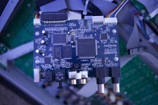
I see on the back of the main input/output pcb (first pic in your first post) a row of 8-soic op amps where access to tools and iron is very good (unlike the front of that pcb where access is blocked by all the connectors). It appears you could choose one of those to swap and experiment on (along with accepting that IF you make a mess, perhaps only that input is lost -- or needs repairing)? (Did that make sense?)
I do reference sound from my Sennheisser HD280s and Ultrasone S-LogicHFI-550 headphones too...
Considering your cans are fairly good, it occurs to me that a headphone amp with a swappable input buffer would be a good way to test different opamps.
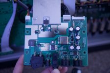
ensen.Your M-audio power supply doesn't seem to be in a ferous steel box. It doesn't appear to have any chokes in or out, either toroid or E-core. Is there something you are not showing us? Ishida Scales packaging machines that use Low voltage strain gauges and op amps are full of this stuff. In fact the Ishida power supplies are around the corner of a 6 gauge square frame from any measuring electronics, with toroids in the input from the AC lines. RF may be acceptable, but I don't like it in strain gauges or audio either. .
- Status
- This old topic is closed. If you want to reopen this topic, contact a moderator using the "Report Post" button.
- Home
- Source & Line
- Analog Line Level
- Help upgrading opamps!