BTW, Douglas Self is also very impressed with the LM4562 and compares it against the NE5532 in his book Small Signal Design. Seemingly (from memory) his single objection is that it costs 10x what the NE5532 costs.
I've read through that book too and (also from memory) can't recall Doug saying that he's ever listened to LM4562 vs NE5532. I agree that the LM posts a very impressive set of measurements. In practice though I've swapped out an LM and substituted a 5532 (in a pair of active speakers I recently bought) and got a much more pleasing sound. I take it this is because the LM is more RF- and layout sensitive. In another design (a DAC) where there's a difference amplifier, again the 5532 sounds better to me over the 4562. I got the 4562 sounding very close to the 5532 by paying attention to RF filtering at the inputs, but as the price is so much higher, I'll be sticking with the humble 5532.
But today you can get a single LM4562 for $3 (at D-K).
At my local market I pay 1RMB (about $0.15) for NE5532 (TI) in small quantities. This part is an audiophile bargain
")
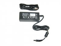
Your M-audio power supply doesn't seem to be in a ferous steel box. It doesn't appear to have any chokes in or out, either toroid or E-core. Is there something you are not showing us? Ishida Scales packaging machines that use Low voltage strain gauges and op amps are full of this stuff. In fact the Ishida power supplies are around the corner of a 6 gauge square frame from any measuring electronics, with toroids in the input from the AC lines. RF may be acceptable, but I don't like it in strain gauges or audio either. .
Well, pictured is the power cord. The mixer itself is a big ole metal housing... the power pcb I showed has some metal plate that sits over it, but doesn't completely surround it.
Attachments
Right, but I got the impression he was trying to be totally objective and not speak about actual listening? From my viewpoint, he was practically raving about the LM4562, saying something along the lines of 'it took 30 years, but finally here's a worthy replacement for the 5532!'I've read through that book too and (also from memory) can't recall Doug saying that he's ever listened to LM4562 vs NE5532.
Yes, that's Doug's forte - THD measurements. I'm rather the opposite - the measurements support the listening but don't supplant it as the end purpose is sound, not signals. Its worthy in terms of its measurements for sure but until its multiple sourced (and hence cheaper) it won't be attractive to volume manufacturers I reckon. As regards sound quality, it doesn't give anything like the bang for the buck of the 5532.
A ferrous (magnetic) steel plate around the switching power supply may mean that M-audio did the 90% of the job that really matters. You'd have to take a scope to the dc output near the op amps to see if any high frequency stuff is getting over there. If not, they are good engineers. They should be, at that price.It is those picky little details that make the difference between pros and the idiots that designed this Herald mixer I've been playing with.Well, pictured is the power cord. The mixer itself is a big ole metal housing... the power pcb I showed has some metal plate that sits over it, but doesn't completely surround it.
Last edited:
A ferrous (magnetic) steel plate around the switching power supply may mean...
It is those picky little details that make the difference between pros and the idiots that designed this Herald mixer I've been playing with.
Um, isn't the supply that stand alone pictured above?
Great news...got the OPA1612 and OPA1642 coming in around 12 PM... Funny thing is, I forgot that I had an old Digitech RP6 guitar pedal laying around (due to broken power supply), grabbed it today, opened it up....lo and behold there are JRC5532s on the Headphone and Main outs... plus they are socketed...found my test subject... Now to get a power supply for this thing... poo another week of waiting for shipment on that.
One of my local charity resale shops (Salvation Army) has a grocery cart full of wall transformers. There will be twenty 3.4V cell phone chargers for anything useful, but I did find a 12 VDC, a 14 VDC, a pair of 9 VDC's, an 18 VDC, and some 30 VDC units for printers. Each was $1. Also try goodwill, St Vincent de Paul, etc, if some are on your daily commute. You make a split supply with two zener diode and some resistors, if your pedal doesn't already have that. For schematic of that see my disco mixer power previously linked to.Now to get a power supply for this thing... poo another week of waiting for shipment on that.
It is a 9v 1500ma AC power supply. Only thing inside was a transformer... I noticed the solder had come loose on one pin, but that didn't fix it... I guess the coil burnt up somewhere... got one on order from e-bay, as I don't know too many places around here that deal with electronics so...
The OPA1612s are here... others on back order.... ordered em as soic which is perfect for the mixer... but the foot pedal is dip... because I am going to use the foot pedal as test subject, I will use a dip socket and solder some leads to adapt one OPA1612 for testing... not much I can do right now, until I get a power supply...
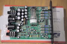
Now you've shown us the PSU is a switcher I'm going to stick my neck out and say that's probably your limiting factor as regards sound quality. There's no sign of any passive filtering of its output (beyond a couple of bog-standard electrolytics) whereas I'd have liked to see chokes. There's also no CM choke on the DC input, just a couple of small Ls which could just be ferrite beads. The Linear Tech datasheet says the LT1370 is a 500kHz switcher - electrolytic caps as used in the picture don't have great ESRs at such high frequencies - ceramics would be called for. Are there any components on the reverse side?
From reading through the LT datasheet for that part, its very much a design for high efficiency. For that it needs fast edges, and fast edges mean a filtering nightmare. Its quite the opposite of what we'd want for audio - LT has some great app notes detailing low noise switching supplies. At the very least it needs serious output filtering and potentially re-regulating with linear regs. At best it should be totally replaced with a linear supply - after all the power demand is not high based on your pic of the PSU brick.
Love the idea of that, but would it be somewhat simple to do
First step would be to measure the voltages and current draws on the various rails.
I totally replaced the power supply in the disco mixer to eliminate hum. See the link above .Wall transformer outside the box, toroid chokes and zener diode regulators and additional filter caps inside the box on a little flying CB that I drilled holes in. Big improvement in hum. Your mixer may have too much current draw for zener diodes regulation, may have to use LM320-xx or something. I bet if you pulled a leg of that big rectifier in the picture, the digital oscillator IC would die. But use a scope on the rails, you should be able to see any oscillation with a 20 mhz or better scope. No oscillation, don't work on it. Takes a good scope trigger, but the B&K 2120 is good enough. Ceramic caps on the M-audio switcher power supply may be surface mount; that is the most common kind now for sale. Look like little bricks with shiny ends in the catalogs. But then, so do SMD resistors. I saw some HF oscillation in my organ preamps at the 60 hz points; had to get rid of the flourescent light on the music rack of the organ and go to white LED's.
Last edited:
Thanks everyone...
Hey guys, just an update here...
I decided not to do anything to the mixer for now...I did switch the JRC5532 in the foot pedal with the OPA1612s, although there is a more clean and midrange sound now, it is pretty minute. It was easy since there were sockets in it.
I purchased an external Behringer SRC2496 AD/DA, an ART tube Mp Project Series preamp and a Rode NT1A mic. Got this stuff so that I could bypass the mixer completely by using S/Pdif.. got a much better sound for vocals. Now I am thinking of modding these items instead, since they cost way less. Ordered a different tube for the preamp (that's a start), from my measurements the tube actually only gets 30v so it is definitely a starved plate design. I may try the opamp switch in the Behringer because the signal from the preamp is a bit hot for the ins of the Beh. Other than that the unit is very clean and sounds good. The Rode literally has 4 caps inside and a pretty decent Capsule, but may be looking into a quick mod similar to the Oktavamod stuff.
Attached is the Black Lion Mod for the original Art tube mp...and a pic of the ART tube mp project series.
Just wanted to thank everyone for their help and ideas on this. If you guys want to help me further I would appreciate it... if not I understand. I will be modding the Art preamp first.
Attachments
Just looked at your pdf.
Without seeing a circuit it's hard to comment but such things as "removing C26 causes a swishing sound from the pot" suggests the cap is needed to prevent DC passing through the wiper... nothing to do with impedance mismatches.
"Many of the caps are biased which helps reduce non linear response of electroylitics" I would question the validity of that too
On this preamp, I was wondering if it is possible to use a transformer to load the tube to atleaste 100v and then drop it back down to 30v to not blow the output opamp. The tube is ofcourse under powered at 30v, so I guess it isn't getting its full sound in the circuit. I got the new tube in the mail today and put it in...it is a Tung Sol 12AX7 which is much quieter than the stock tube so poo.. it's always something.
- Status
- This old topic is closed. If you want to reopen this topic, contact a moderator using the "Report Post" button.
- Home
- Source & Line
- Analog Line Level
- Help upgrading opamps!