Why are R205 and R176 so high?
<=1k would be more suitable.
no idea, behringer designer might be able to answer it. btw nu3000dsp is not a diy amplifier.
great, i find nu3000 schematic and it seems has Zin 20k. so total Z (47k,100k,20k) should be 12.3k. my IC use canare LV-77s which has capacitance 67pF/m and 1.6m length, then each IC has 107pF. is it still safe?
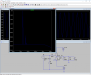
Zin=R205+R194=30k actually so no less than 15.44k combined with the two other amplifiers. 3x10⁷pF say around 330pF-350pF including the termination parasitic capacitance. I saw no problem in the simulator driving that, the THD looks good at 1 and 2V RMS (1VRMS sim attached). Frequency response simulated still very wide also.
To learn about the line driving realities for any system read this RANE note: Practical Line-Driving Current Requirements
Attachments
Thanks Salas, that is really great info.
You are welcome. Although the RANE examples are from the sound reinforcement industry for very long cabling and very high signal levels, the formulas there are universal to plug any different home story numbers.
That's a 7.5mS min to 12.5mS max gfs and 12nVsqrtHz noise part. It won't achieve as good performance as the 35ms and 0.95nVsqrtHz Toshiba part when at 7-8mA IDSS selection. It will also be thermally pushed when chosen for its max gfs samples due to its larger IDSS for that. Of course its a handy monolithic offering automatic pair match. Will still have to be selected for in vicinity IDSS samples between channels though. For both channels to have similar performance. But it will bring noticeably inferior THD and noise results vs an original parts DCB1. Not unusable as a buffer JFETs pair, just not in the same class.
That's a 7.5mS min to 12.5mS max gfs and 12nVsqrtHz noise part. It won't achieve as good performance as the 35ms and 0.95nVsqrtHz Toshiba part when at 7-8mA IDSS selection. It will also be thermally pushed when chosen for its max gfs samples due to its larger IDSS for that. Of course its a handy monolithic offering automatic pair match. Will still have to be selected for in vicinity IDSS samples between channels though. For both channels to have similar performance. But it will bring noticeably inferior THD and noise results vs an original parts DCB1. Not unusable as a buffer JFETs pair, just not in the same class.
Ok- Thanks for the answer, Salas
Hi,
I'm considering building a DIY power amplifier. As an option there will be High Pass filter to cut off the lowest frequencies (70 Hz) and output terminals for external bass amplifier. I'm planning to add DCB1 buffer before HP filter to avoid problems with impedance. So the signal path would be:
shunt attenuator(50k)->voltage amplifier->DCB1buffer->HP Filter->Current amplifier.
Usually DCB1 is used for input signals 1-2V RMS. In my case signal after the voltage amplifier will be 30-40V RMS. Should I apply different parts values of hotrodded DCB1 in this case? (eg different resistors values in the buffer or different symmetrical voltages). Please advise.
TIA & regards,
bern
The DCB1 as it is (+-10V rails) can swing 6.71V RMS max before clip (19V peak to peak). Will still stay below -80dB THD (0.01%) at such a signal voltage level which is a generally agreed non directly audible threshold. But the harmonics will be denser and equal now. No even ones will be dominating the odd ones anymore.
40V RMS is 113V pk-pk demanding +-60V rails and for such enormous swings I would recommend a design resembling the buffer stage right after the driver stage (VAS) of a 200W at 8Ω solid state power amp or the cathode follower after the driver stage of an analogous grid voltage swing tube amp.
40V RMS is 113V pk-pk demanding +-60V rails and for such enormous swings I would recommend a design resembling the buffer stage right after the driver stage (VAS) of a 200W at 8Ω solid state power amp or the cathode follower after the driver stage of an analogous grid voltage swing tube amp.
I think the signal path over and came to the conclusion that DCB1 might be placed before the VAS.
So the path could be as in the following diagram:
Do you think it could work?
Regards,
bern
So the path could be as in the following diagram:
An externally hosted image should be here but it was not working when we last tested it.
Do you think it could work?
Regards,
bern
The DCB1 has an output impedance of ~200 ohms
That finite value should be used to determine what effect that has on the following filter circuits.
I would move the DCB1 to before the filter bypass switch.
Values of 100k and 47k may be too noisy for the high pass filter.
I suggest you aim for ~10k
That finite value should be used to determine what effect that has on the following filter circuits.
I would move the DCB1 to before the filter bypass switch.
Values of 100k and 47k may be too noisy for the high pass filter.
I suggest you aim for ~10k
Last edited:
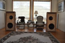
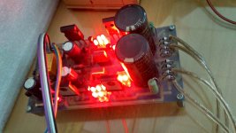
Build is straight from BOM using Panasonic caps that took months to acquire. Room filling sound that puts you there. We have been to quite a few live venues and this is comparable. Awsome. Open baffles are bi-amped
Attachments
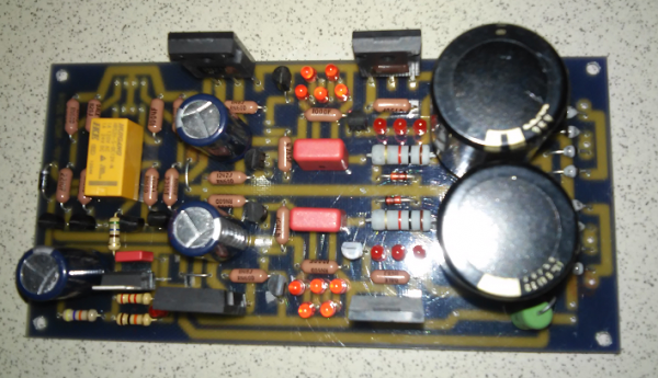
Which schematic you used? It does not look like a DCB1.Build is straight from BOM using Panasonic caps that took months to acquire. Room filling sound that puts you there. We have been to quite a few live venues and this is comparable. Awsome. Open baffles are bi-amped
Thanks Stixx
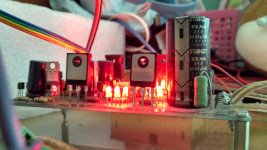
my board almost finished. here it is :
I forget to buy BC550 and BC517.. I have some BC547. I think it can be used to replace BC550, but I dont have any idea with other transistor to replace BC517.
I have to go to bed now... still feel some pain..need some rest.
I'm happy with my board progress. wish I could finish it in my dream heheheh
almost 3 years
superb 3D sound from this pream. Thank you Mr. Salas
Attachments

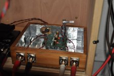
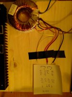
Hello, I am close to finishing my first DCB1 build. Before I connect the board to the 2x15V 50VA transformator, however, I want to ensure I understand the wiring correctly. I connected the two primary sides in serial due to the 230V net. I also connected the secondaries in series resulting in the resulting in the three wires shown on the first picture. Those three are connected to the DCB1, right? The middle one serves as center tap and the polarisation of the other two wires is irrelevant?
The sexond picture shows the finished DCB1 build. Is there anything you recognize as obviously wrong? I don't want to blow up my work due to a stupid mistake") .
.
Thank you.
PS: I already uploaded the pictures in another thread.
Picture1: http://www.diyaudio.com/forums/atta...1-preamp-build-thread-img_20180120_000448-jpg
Picture2: http://www.diyaudio.com/forums/atta...1-preamp-build-thread-img_20180120_000554-jpg
The sexond picture shows the finished DCB1 build. Is there anything you recognize as obviously wrong? I don't want to blow up my work due to a stupid mistake
.Thank you.
PS: I already uploaded the pictures in another thread.
Picture1: http://www.diyaudio.com/forums/atta...1-preamp-build-thread-img_20180120_000448-jpg
Picture2: http://www.diyaudio.com/forums/atta...1-preamp-build-thread-img_20180120_000554-jpg
I have the Mesmerize PCBs.
They have the middle terminal as the Centre Tap connection.
I can see the Zero Volts passing along the centre line of the PCB.
Is your PCB similar?
Before you connect up Power on the transformer with a Mains Bulb Tester. Check the AC voltages, both halves and then total.
Power OFF. Connect the three transformer secondary wires to the PCB and power ON. The bulb filament may not flash at all or may glow brightly for a second or two and dim quickly to virtually off. measure the voltages on the smoothing capacitors. Check they are not reversed and check the total voltage from V+ to V-
If these are all OK, then power ON direct from the mains.
I have the "DCB1 Hynotize Hot-Rod buffer" PCB from Tea-Bag (the black one at the top in this entry: Salas HOT ROD DCB1 - diyAudio).
I want to connect the three wires from the picture below to the PCB. The middle connection between the two secondaries (connection of red and orange) as center tap.
I measured AC between the black and center tap and yellow and center tap as 15-17 V.
I want to connect the three wires from the picture below to the PCB. The middle connection between the two secondaries (connection of red and orange) as center tap.
I measured AC between the black and center tap and yellow and center tap as 15-17 V.
As far as I understand it, I put a light bulb in series with each of the three wires coming from the secondaries, right? Sounds like a great mechanism to protect the circuit.Before you connect up Power on the transformer with a Mains Bulb Tester. Check the AC voltages, both halves and then total.
Power OFF. Connect the three transformer secondary wires to the PCB and power ON. The bulb filament may not flash at all or may glow brightly for a second or two and dim quickly to virtually off. measure the voltages on the smoothing capacitors. Check they are not reversed and check the total voltage from V+ to V-
Attachments
- Home
- Source & Line
- Analog Line Level
- Salas hotrodded blue DCB1 build