The CCS and the Shunt devices need cooling.
You would have to mount all four power devices on the side walls.
What about picking out a long narrow case where the side walls are much closer together.
yes, thats exactly what I wanted to do. So mounting the power devices on the sidewalls and connect them with cables.
I wanted to have this kind of case due to optical reasons...
Avoid cable extensions to the MOSFETS pins. Their length inductance can provoke oscillation. Mounting on a thick enough chassis floor is usually very capable up to moderate hot-rod 200-300mA. If you have to do extensions keep them shortest possible and have each gate resistor short legged and soldered directly at the gate pin. That involves removing them from the board and wiring for them gate resistors from their original input side pad. Again non oscillation chance is not guaranteed but possible to escape.
The Hypnotize version, maybe Tea-Bag has some left. The Mezmerize version, is on the diyA store.
Thanks! I would prefer Hypnotize, don't want multiple inputs.
that makes for a risky combination.Hi,
Sorry my stupid question: where can i get these dcb1 pcb's or similar? I already ordered B1-parts but i don't like to have any capacitors along signal path, as my aleph 5-clone monoblocks doesn't have any either.
Thanks.
What alarms/protections are you putting in place?
that makes for a risky combination.
What alarms/protections are you putting in place?
Hi,
Yes, there is a risk of high dc to speakers? I have 3sec boot delay/instant disconnect when power off and dc-prot boards in both of Alephs.
When you turn it off, you will get high DC on output (as I remember 300mV+ for about 2-3 seconds).
Yes, but dc-prots won't let it go through, plus they disconnect speakers immediately when powering off
") so it doesn't matter as long as dc-prots are working as they should.
so it doesn't matter as long as dc-prots are working as they should.Yes, there will be no problem if the B1 and the amp turns off the same time.
Takes also about 3-4 seconds for the DC to rise. Depends on supply cap size. If there is DC prot, then it will also help, just not a good thing to rely on prot every time they are turned off. Better to calculate in advance.
Takes also about 3-4 seconds for the DC to rise. Depends on supply cap size. If there is DC prot, then it will also help, just not a good thing to rely on prot every time they are turned off. Better to calculate in advance.
Has it?The dcb1 has an instantly output disconnecting relay at power off
I don't recall a circuit to deactivate the output relay on loss of AC.
I think the output relay drops out as the supply voltage from the regulator drops below the relay drop out voltage. Since there can be very little current draw from this regulator other than the relay, there is no way I could agree that this is an instant OFF output relay.
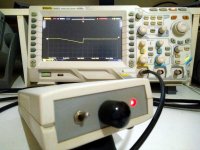
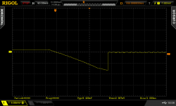
When throwing the power switch off it takes 0.23sec from zero crossing before disengaging back to zero. Reaches -8mV max. Measurement settings are 50ms/5mV XY in hi-res mode single trigger event capture of the output. As seen in the screenshot attachment. That's all what happens with my (still at 1mV offset after nine years without trimming) original DCB1 prototype during power down. In my view "instant" enough and safe enough for any practical purposes.Has it?
I don't recall a circuit to deactivate the output relay on loss of AC.
I think the output relay drops out as the supply voltage from the regulator drops below the relay drop out voltage. Since there can be very little current draw from this regulator other than the relay, there is no way I could agree that this is an instant OFF output relay.
Attachments
Trying to see if I can post a pic by using a link from my Google Photos as I have some questions about my build and Photobucket seems impossible to use anymore...please be patient.
Ugh...didn't work...anyone have a recommendation on a free pic hosting source that doesn't bog down with pop up adds and crash your browser?
Ugh...didn't work...anyone have a recommendation on a free pic hosting source that doesn't bog down with pop up adds and crash your browser?
Attachments
Last edited:
 I have helped you by adding it as an attachment. Use the go advanced answer mode to find the attachments menu. Its better loading it here, it stays.
Thanks much Salas...I had no idea that was even possible. You managed to grab the link and get it to work before I could delete it.
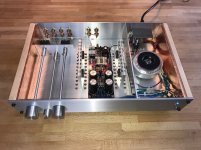
Thank you for the compliment. Construction is important to me. I do my best to try and look at others work first and reflect what I think seems right. This is also very much a creative outlet for me as I have a background in the arts that I seperated from quite some time ago.
I worked on it for a little over a year fabricating everything I could from scratch. I finished it sometime in February.
I reviewed all the information I could glean from this thread and other notes you published relating to this project many times. I do have a few doubts about my understanding related to grounding/signal connection choices and whether or not I made proper decisions concerning them.
I followed start up recommendations and took measurements several times. At initial start up I measured V+ and V- at 9.61 and -9.61 respectively. After 5 min I measured again and they stabilized at 9.5 and -9.5 respectively. After about 15 minutes of idling the results appeared to remain the same. DC offset for the right and left channels was -1.7 and -1.4 respectively. Again, I measured after about 5 and 15 minutes and they stabilized at -1.8 and -1.7 respectively. The relay clicked as it was supposed to. I decided it was OK to try and use it in my system. I believe you stated it was preferred to have one of the voltage measurements slightly higher or lower than the other?
I've been using this as a preamp in my experimental system. The primary amplification used is a gainclone that I built from one of Peter Daniels premium kits. The chip amp plays into a pair of Tang Band W8-1808 drivers mounted in DIY Oris 200 horns that I cobbled together. I try to supplement the horns with a subwoofer that has a built in plate amp with crossover. I also have a MiniDSP I have tried using to control things. I have a temporary solution for my phono in the form of a Boozehound phono amp to play records through this system. I also connect my apple devices to the preamp and stream Pandora at times. This system is really just put together as a work in progress and for my learning purposes.
All seems well and sounds good with this combination given the fact that it is far from a scientific assembly.
However, I am having issues with noise that became apparent when I tested a pair of Lowther DX3s in this system that I purchased over the winter.
It was a while ago that I tried the Lowthers, and I went back to enjoying the Tang Bands. I know I was able to track some noise to a bad power supply running the MiniDSP and phono amp, which I eliminated and replaced with NiCad power supplies I had.
The experimentation left me thinking the noise might have something to do with how much gain the chip amp had as it was obviously so powerful that the volume could barely be raised on the preamp.
I continued experimenting by replacing the chipamp with a pair of Quicksilver Horn Mono tube amps between the DCB1 preamp and the Lowthers...which didn't work either.
The Lowthers only seemed to play quietly with the tube amps if I replaced the DCB1 pre with my old Audible Illusions tube preamp.
This left me scratching my head and wondering if the DCB1 was completely incompatible with the Lowthers or tube amps or both. I need to repeat my experiments again to make sure I am recalling it all correctly, as this was done back in February.
In the mean time any insight you could offer would be greatly appreciated.
Regards
Kevin
Are your double mono volume pots logarithmic type for sure in the DCB1? Linear pots can open up the volume fast. As a circuit it has no voltage gain as it is a buffer.The Lowthers only seemed to play quietly with the tube amps if I replaced the DCB1 pre with my old Audible Illusions tube preamp.
The DCB1 has a gain of +0dB
The system gain with your very high efficiency speakers is probably too high and that is leading to two difficulties: Excessive noise/hum and a large part of the vol pot range that is unusable.
Have you read ?
http://www.diyaudio.com/forums/diyaudio-com-articles/186018-what-gain-structure.html
You probably need a very low gain Power Amplifier. Maybe worth investigating "Power Follower".
- Home
- Source & Line
- Analog Line Level
- Salas hotrodded blue DCB1 build