Are your double mono volume pots logarithmic type for sure in the DCB1? Linear pots can open up the volume fast. As a circuit it has no voltage gain as it is a buffer.
I contacted the seller that I sourced the mono Noble pots from as I could not remember...he custom ordered them from Noble in the 90s and had NOS surplus.
He tried to track down specs using numbers he had, but was unable to definitively confirm the fact that to his recollection they were actually linear taper pots.
Not sure where to go from here as they seem to be OK in the system with the Tang Band drivers. I have some Alps pots I'm not exactly excited about using, and also some cheap Chinese stepped attenuators. Swapping the pots out to try and reduce the noise issues I experienced during testing with the Lowther drivers seems an unlikely prospect though.
As far as gain issues, I have run into the subject in several threads. I read the article Andrew linked to. I can regulate the output of my digital source prior to the preamp, and there is no other gain stage besides the chip amp. The Boozehound step up may be pumping out more gain than it should with a 24V battery supply. I was using a 19V laptop supply to power it, but I discovered it was contributing a lot of noise to the system and in actuality only producing about 16V. As I mentioned, it is a temporary solution as I already have everything in place to build the Simplistic Phono. I was using a Clearaudio Virtuoso wood on my turntable. It is said to have a 3.6mV output. The turntable is currently undergoing an overhaul/refurbishment...so I can't do any further testing with it right now.
Measure them division across enough positions and plot a graph so to establish if they are linear or log. Its a very important thing for apparent SPL. Linear pots pass most of the available volume in the first quarter of their rotation as far as the human ear is concerned. BTW about noises when with very sensitive speakers, is there any wire for referencing the chassis to the PCB zero? Either straight to it or through a 10-100 Ohm resistor? If not, test that, it may help. If helpful indeed, remove the simple test wire, solder together two 5A diodes in parallel but with their stripes at opposite ends, parallel a 10 Ohm 3W and a 0.1uF film cap to those. Bolt one end of that safe ground lifting/zero reference system to chassis and wire its other end to a PCB zero. There is a convenient zero middle pad marked G in the regulators output vicinity between V+ & V- pads.
I tested resistance at several positions of two extra 20k Noble pots I purchased at the same time and compared them to the 20K Alps RK27 I have on hand. They are completely different throughout the range and appear to have a linear taper as I have read descriptions of. At 50% of total rotation they measure 50% of total resistance.
I will have to decide if I want to use the 20K RK27, the 25K eBay stepped attenuators or seek out something else. The real disappointment is thinking I had scored a find in the Noble pots at a good price and now I will have to pull things back apart and refit something else...and it seems impossible to find quality pots at a reasonable price.
These are the notes I tried to follow when doing the signal and ground wiring:
+RCA IN to pot IN. RING RCA IN TO POT GND. Repeat for channel 2. No link between rings.
POT WIPER pins channel OUTputs to DCB1 INputs. POT GND pins locally linked. One wire from them to DCB1 middle pin IN (GND).
DCB1 OUT1, GND, OUT2 to RCA OUT1+, 0(linked rings), RCA OUT2+
RCAs insulated.
IEC EARTH PIN to chassis (short link). DCB1 to chassis can ground from ground linked POT's body. Or a sturdy link from Vout middle tap to chassis, and the pot will find ground when attached to chassis without GND PINs to body link.
I believe they were copied from a response you posted early in the thread.
I interpreted them as meaning that if ground was found on the board via the pots that there was no need to add another grounding point. I was also worried about creating ground loops. In reading the notes again now I am still not sure I understand what was meant.
I also questioned my understanding of the "No link between rings." statement, as I had 4 sets of inputs and it did not seem sensible to run seperate wires from all those RCA rings to the same pot ground when connecting them first and running one wire would seem to serve the same purpose. I am only switching the +RCA source signal with the Grayhill selector. I did keep the RCA ring grounding seperated between channels.
There is not currently a ground from chassis to the Vout middle tap. I will follow your instructions and test with this grounding you are suggesting.
Thank you for taking the time to offer help.
Regards
Kevin
Last edited:
If the chassis and the signal ground shows continuity with the DMM buzzer test as is, then the pots metal body parts are already grounded and they are not a source of noise because floating.
The ebay switchers are very decent in performance for the price but weak in construction and their resistors aren't top notch. Better mechanically and smoother in sound are the 24 step 25K Goldpoint Log. But several times pricier. Another interesting maker of costly pots is Khozmo from Poland. I have used both makes in 20K ebay 21 steps and in 50K Goldpoint 24 steps. In DCB1 and DCG3. The Goldpoint tends to open up in volume later than the ebay pot regarding their Log taper's aggressiveness.
The ebay switchers are very decent in performance for the price but weak in construction and their resistors aren't top notch. Better mechanically and smoother in sound are the 24 step 25K Goldpoint Log. But several times pricier. Another interesting maker of costly pots is Khozmo from Poland. I have used both makes in 20K ebay 21 steps and in 50K Goldpoint 24 steps. In DCB1 and DCG3. The Goldpoint tends to open up in volume later than the ebay pot regarding their Log taper's aggressiveness.
If the chassis and the signal ground shows continuity with the DMM buzzer test as is, then the pots metal body parts are already grounded and they are not a source of noise because floating.
Yes...I do have continuity between my signal grounds and chassis. That is why I thought I did not need to add another ground wire at the Vout point on the DCB1. Should I still try adding the extra ground strap at the Vout center pad?
The ebay switchers are very decent in performance for the price but weak in construction and their resistors aren't top notch. Better mechanically and smoother in sound are the 24 step 25K Goldpoint Log. But several times pricier. Another interesting maker of costly pots is Khozmo from Poland. I have used both makes in 20K ebay 21 steps and in 50K Goldpoint 24 steps. In DCB1 and DCG3. The Goldpoint tends to open up in volume later than the ebay pot regarding their Log taper's aggressiveness.
Yes that is exactly what my impression is of the eBay options. They are not really what I want to use in this project given the time and parts I have invested in it. I bought the eBay options because they are cheap and easy to experiment with. I have looked at exactly the same options as you mention, but the $175 for a Goldpoint or Khozmo is a pill I have not been able to swallow yet. Actually, dual mono pots would run me more like $200+. Parts Conexxion has TKD pots for about $45 I believe, but I would have been happier if I had found the correct Noble pots...even at that price.
I recently found these EIZZ Chinese made attenuators on eBay, but I know nothing about them...
EIZZ 25K 24 Step MONO Attenuator Volume Potentiometer Audio HIFI Amplifier | eBay
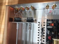
Here is a slightly better pic of my signal/ground wiring for reference...
Attachments
The EIZZ states BH 1/4W Carbon resistors. Better not, DCB1 is about transparency its not a guitar tone stack. Does not clearly state "Log" also, but when they state "Audio Attenuator" they usually imply Log.
If you like to try carbon nonetheless and you had 100K or 250K good quality linear pots, say Tocos, then a smaller value high quality resistor (order of magnitude less i.e. 10K or 25K) added in parallel to a pot's output would have given it a Log like curve. Approximately. It would also average the tolerance between mono pots.
Try the tiny ebay switcher pots you already got I would say just for a test at least. To know what to expect for volume response and channels balance.
In general there is wide loop area in your input wiring since its not done with twisted pairs, maybe better if not done with RCA rings ground bus wires but with individual inputs wire pairs heading to the switch while their zero returns star grounded all together at an eyelet fixed to that screw and nut in the middle of the mounting sub-panel.
About the chassis zero reference you already have, try adding 10 Ohm series resistor ground loop breaker if there are little suspicious noises in the background reminding of loop buzz. Maybe a 0.1uF film cap in parallel also. It may also prove better to undo the now input side chassis reference wire(s) and replace with one from that central V zero point pad on the PCB.
The single wires from input sockets to attenuators are not right......................
I recently found these EIZZ Chinese made attenuators on eBay, but I know nothing about them...
.................
Here is a slightly better pic of my signal/ground wiring for reference...
Each input circuit loop is acting like an aerial picking up whatever interference is inside the chassis.
The input circuit for each input when selected must be a close couple signal pair. No big loops, not even at the terminations.
The same problem for the outputs. Eliminate the big loops.
In general there is wide loop area in your input wiring since its not done with twisted pairs, maybe better if not done with RCA rings ground bus wires but with individual inputs wire pairs heading to the switch while their zero returns star grounded all together at an eyelet fixed to that screw and nut in the middle of the mounting sub-panel.
I haven't had a chance yet to go back and re-test the system with the Lowther drivers to make sure I have everything straight in my head about my attempts to isolate sources of noise. I'm in the middle of a turntable project and am trying to work on one thing at a time...but I am very much preoccupied with figuring out what to do about the preamp...if anything. I wanted to comment on this wiring issue since both you and Andrew mentioned it, and I had doubted my decision concerning the wiring.
I was aware of the standard practice of "twisting pairs" for the purpose of minimizing noise induction to signal wiring before I started this project. I had implemented the technique in other projects previously. However, none of those projects involved switching sources. I couldn't find any solid guidance on the subject in the thread or elsewhere, except that the Mezmerize was available as an option with switching relays.
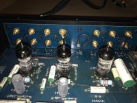
I looked at as many builds as I could and came across several that had used bus style wiring for the grounds. I also opened up my AI Modulus preamp and took a look at what they did...which it seemed to me to amount to a similar technique, but in hindsight appears to use a separate PCB as a means to star ground inputs to one point...there is no twisting of signal wiring in it.
My question is this...if the decision to not twist signal pairs is so wrong, why would a HiFi designer not use the technique in their well known and fairly respected product?...and if the non twisted signal wire is a source of noise that I experienced when experimenting with the Lowthers, why did I not hear any similar noise from the Tang Band drivers even when I turned the volume to its maximum? The only noise I heard at max volume with the TBs was a slight hiss when I put my ear up to the exit of the front horns. I've attached a pic of the AI preamp internals below for reference.
About the chassis zero reference you already have, try adding 10 Ohm series resistor ground loop breaker if there are little suspicious noises in the background reminding of loop buzz. Maybe a 0.1uF film cap in parallel also. It may also prove better to undo the now input side chassis reference wire(s) and replace with one from that central V zero point pad on the PCB.
Just to clarify...I did not add ANY additional input related chassis reference. My interpretation of the grounding recommendation wording you posted earlier in the thread was incorrect I think.
I thought that the body of my pots (being made of metal) was functioning as a grounding point. I thought that once I connected my input signal wiring to my source selection switch and then to my pots along with the ground bus wires directly connected to the pots that I had a ground reference from the bus wiring of the input RCA rings to the chassis, I was incorrect.
I quickly retested the grounding with all inputs and outputs disconnected as well as the power cord removed. There was continuity throughout the PCB and between the input and output ground bus wiring, but no continuity to the chassis.
When I disconnected the input wiring between the pots and the PCB all grounding was isolated to the input ground bus wiring and pot wiring. When I then reconnected all the input/output wiring to the PCB, plugged the preamp in and connected it to my gain clone I got ground reference to the chassis. I'm assuming this was due to a ground loop through the power cords and interconnects between the preamp/amp. This may have been happening through connections with other equipment as well regardless of using a battery as the power source.
I suppose my first/next step should be to install a proper chassis ground reference at the Vout center pad. Should I automatically include a safe ground/loop breaker of your recommendation? I'm wondering if I should be trying to connect all ground references to the same point if possible? Including the input wiring if I were to revise it with twisted pairs? It would require some kind of compromise regarding the ground wiring I think.
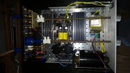
Currently there is only a ground reference for the IEC power inlet and also one for the transformer shield. I read the shield should not be connected to that same chassis ground point, but rather somewhere close in proximity to the transformer.
Attachments
We don't know what differentiates with the Lowthers beyond they are obviously very sensitive transducers. Some peak or plateau that further highlights an improvable area of little background noises when your new preamp is connected? Possibly.
There are the practically acceptable and the optimum wiring ways. Optimizing can offer a few dB better noise-floor or not. Its application specific if critical. Each manufacturer decides performance gains vs most practical assembly. We wouldn't be thoroughly responding your questions if not mentioning wiring optimization alternatives since you noticed some noises. Without solid data we are just making suggestions of course.
Regarding ground strategy and chassis, the loop breaker resistor helps against interactions with other equipment. Lifting with diodes still has that resistor, it just adds a way to open and bypass it for dumping large current to the protective earth via the chassis in a disaster scenario of power components hard short failure. Not to try find that mains earth through interconnect shields to another mains earthed chassis. Wise to have but it does not make a difference regarding signal ground to chassis referencing.
Shorter transformer shield wire to chassis is best due to its lower inductance. In other words allowing a much better escape path to higher frequency interference possibly collected by the shield.
- Home
- Source & Line
- Analog Line Level
- Salas hotrodded blue DCB1 build