Hi Andrew, thanks for the suggestions. Please keep in mind that I'm relatively clueless compared to you guys. You lost me at the bit about the relay, but I think I did that maybe? The diode next to the relay (1N004) correct? Voltage (one probe on diode leg, other on the V+/- ground pad) gives me 9.5V on both sides.
Regarding the transformer: it has dual secondaries for 30v or 15v operation. The data sheet says to jumper them in parallel for 15v or jumper them in series for 30v. This is what I meant by paralleling the secondaries. You don't think I should be doing this?
Thanks Andrew, I'm probably going to test you patience here.
-Adam
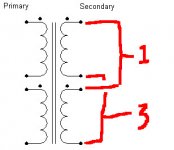
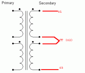
DCB1 has symmetric supplies. It needs one secondary feeding each side. You should connect them in series to the DCB1's connector. See picture. On voltage drop across the current setting resistors, you just have to measure it across each one's legs. No GND reference consideration.
Attachments
Your 9.5V at the relay diode confirms you have far too a voltage at the 12V regulator.
This is probably because you have wired the transformer to PCB incorrectly.
Hopefully Salas' sch will get you right.
The relay voltage after triggering should be the same as the regulator voltage less the drop through the switching transistor.
The voltage at the regulator input should be around 20Vdc to 23Vdc depending on mains voltage.
Tested my newly built DCB1 today, i have 9.75V and -9.74V, relay clicks, and around 0.3mVDC in left channel, 1.5mVDC in right. Haven't had a chance to listen to it yet, but these values are no cause for concern, right? Measured when the DCB1 had been powered around 20 minutes, using 10R CCS resistors. Everything seemed cool to the touch except the resistors, which were warm.
I used a kit from Teabag, but opted to use ~11mA Idss for the matched quad LSK170, i know this is on the high side, am i sufficiently biasing these JFETs? It was the most tighly matched quad available to me.
I used a kit from Teabag, but opted to use ~11mA Idss for the matched quad LSK170, i know this is on the high side, am i sufficiently biasing these JFETs? It was the most tighly matched quad available to me.
Incorrectly wiring the transformer risks severely damaging either the transformer, or the circuit.
Did you use a Mains Bulb Tester for all your Power ON?
No I did not try the mains bulb tester -- I simply just fired it up. Perhaps not a good idea but it seems okay.
I had the transformer hooked up as in the attached pic (nothing to CT/02). It was exactly like the data sheet suggested to yield a 15v ouput. I failed to extrapolate how this would work when going into a symmetrical psu, like what Salas pointed out however.
All seems well at the moment!

Last edited:
Volume control for balanced DCB1
As I really like the sound of my balanced DCB1, I am slowing thinking of expanding the functionality with a volume control after hotrodding it some more. Possibly.
I remember to have read in a former post that implementing a volume control for a balanced DCB1 is not so easy, due to impedance matching, grounding, etc. (cannot find the post at the moment). AndrewT even suggested to go from balanced to unbalanced, control volume there and go back to balanced again.
Do people have further experience on this subject and has someone found a relatively easy way to overcome this hurdle? What about just using a quad stepped attenuator (such as goldpoint) with 0,1% resistors?
Or am I misunderstanding anything here?
Hi guys, back again...
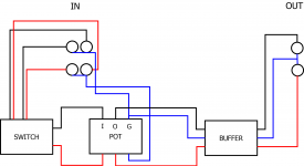
This time I have a question about the ideal grounding scheme for the DCB-1 when a switch and pot are used before the input of the buffer. My DCB-1 is working quite well but there is a very very slight ground buzz coming from it. It is acceptably quiet, but I would like to improve it if possible.
I have 2 sets of RCA inputs going to a rotary switch (with no ground lugs) which goes to a stereo (Noble) pot with ground lugs for both channels, which then goes to the input of the buffer.
I have attached a rough diagram of how I have the signal grounds implemented at the moment. Probably not ideal-- was just a bit of a stab in the dark to be honest.
What do you guys think?

I think a photograph would give a better idea of your actual layout. I had low level hum too so i rewired using a twisted pair from each RCA socket. The input selector switches both the feed and return for each channel. The signal returns are common at the pot with very short tails from pot to board. That did the trick.
The switch type i used - http://www.ebay.co.uk/itm/Alternative-to-Peco-PL-21-4Pole-Double-Throw-Switch-SW320-/150522990363?
The switch type i used - http://www.ebay.co.uk/itm/Alternative-to-Peco-PL-21-4Pole-Double-Throw-Switch-SW320-/150522990363?
Last edited:
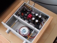
Thanks for the reply. I've attached a pic of the build -- hopefully it will give an indication of my methods here. Since this pic was taken I've added ground runs from the inputs to the GND lugs on the pot, which are shown in my illustration in the previous post. And to clarify, the leftmost 2 rca jacks are inputs, the right two are outputs (one is a direct 'split' off the switch, and the other is the output of the buffer). Input grounds are NOT tied to output grounds there. My switch does not have a place for grounds.
What do you think? I know its a little messy. My signal wire was much larger gauge than necessary so it adds to a bit of clutter -- it's good mic cable though.

What do you think? I know its a little messy. My signal wire was much larger gauge than necessary so it adds to a bit of clutter -- it's good mic cable though.

Last edited:
I'd use smaller diameter signal wire with more twists per inch. Also try twisting your mains wiring together and the transformers secondary wires feeding the board. You could also try moving the transformer and turning it round too in case it's affecting your volume pot. I found it best to have the area where the primary & secondary wires attach facing away from volume pots and signal wiring.
Nice case btw, you should be able to get a great result with a bit of trial and error.
Good luck.
Nice case btw, you should be able to get a great result with a bit of trial and error.
Good luck.
Last edited:
Thanks for the tips. Perhaps I will re-wire the i/o the next rainy day I have. Unfortunately I can't turn the torodial or else the primary leads won't reach the IEC socket. Twisting the secondary leads is easy enough though.
The case is actually from Peter Daniel's integrated chipamp kit he used to sell. I re-purposed it for this project since I decommissioned the chipamp.
Thanks again!
The case is actually from Peter Daniel's integrated chipamp kit he used to sell. I re-purposed it for this project since I decommissioned the chipamp.
Thanks again!
- Home
- Source & Line
- Analog Line Level
- Salas hotrodded blue DCB1 build
