Don't know the thermal resistance of Kapton high temp tape. If its more than 1C/W that a common Silpad achieves, better avoid. Paste for Mica like films, yes. For Silpads, no.
I've read that kapton & mica are the best insulation between device and heatsink. Tried to find the link, but was unlucky.
I don't follow the above sketch easily, but in words, you should tap off from DCB1 (in) after the pot to a couple of extra outputs when needing non buffered attenuated outputs beyond the buffered attenuated normal ones you get from DCB1 (out).
it's vice-versa actually

I need:
1. only the buffer
2. buffer + attenuator
the scheme shows both combinations with different colors marked. It would work in that way, though I'm not sure if that is the correct way of wiring
How about those Aluminium Oxide Ceramic insulators? I am using them with a thin layer of thermal paste on the DCB1, are they suitable for hot rod?
Don't know, you should look up their thermal resistance. If its below 1C/W they will be better than Silpads. Best is Keratherm Red if there was a difficult situation, but we have allowances here still.
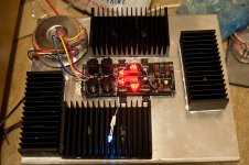
Well I have done some testing and the present heatsink layout is adequate with hopefully enough headroom to compensate for enclosing everything in box.
I know vertical fins are better, but it will significantly reduce the contact surface with the bottom plate (to which the fets are attached).
There are also 2 heatsinks attached at the bottom of the plate, and the plate/side walls are elevated 3cms to allow it to breath from the sides
About air circulation, I intent to open some slots on the side walls to allow air flow in. And the top will be open in the middle, forcing the air move from the bottom sides to the top center.
If you are only running Shunt Reg at <~500mA you should be OK. Above that and your MOS-FETs are going to get VERY hot. Mine run nice and cool at 300mA, above that they start to cook.
Attachments
it's vice-versa actually
I need:
1. only the buffer
2. buffer + attenuator
Then you should use a switch shorting the attenuator or not.
If you are only running Shunt Reg at <~500mA you should be OK. Above that and your MOS-FETs are going to get VERY hot. Mine run nice and cool at 300mA, above that they start to cook.
I m running it at 1,2A and the temperature after 2 hours was about 50C on the case of the fets.
And that was with just the plate and the heatsinks just left on top of it. Not screwed on it, no thermal paste and no bottom heatsinks.
It s the aluminum plate that makes a significant difference.
I just hope the extra measures will be enough to compensate for closing the box
Last edited:
More work today... Took me more than I expected... that damn thermal paste is all over the place
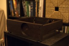
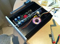
The chassis is glued together and finished with 120 grit sandpaper (It feels way smoother than it sounds...). I also put a layer of oil/wax and the wood got a nice dark color. The damn photo again is not doing it justice. I plan to do an additional layer tomorrow and after it dries I will put everything together.
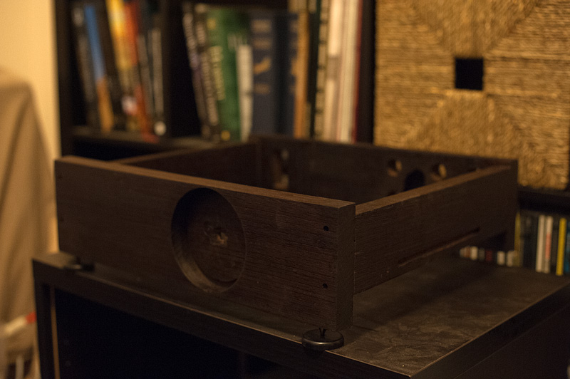
You can also see the side vents and the spikes. I intent to make some smaller plates for them.

The heatsinks were properly screwed in place along with the Caddocks that are now below the pcb screwed to the plate themselves.
I also removed all wiring to replace it with pure silver and I added a white led which will show on the front panel.
The chassis is glued together and finished with 120 grit sandpaper (It feels way smoother than it sounds...). I also put a layer of oil/wax and the wood got a nice dark color. The damn photo again is not doing it justice. I plan to do an additional layer tomorrow and after it dries I will put everything together.
You can also see the side vents and the spikes. I intent to make some smaller plates for them.
The heatsinks were properly screwed in place along with the Caddocks that are now below the pcb screwed to the plate themselves.
I also removed all wiring to replace it with pure silver and I added a white led which will show on the front panel.
Attachments
Depends on the eyes !
Sorry I didn t build one more aluminum faceplate with heatsink sides
I've read that kapton & mica are the best insulation between device and heatsink. Tried to find the link, but was unlucky.
found some info in the net. It's 0.71 1 W/(m.K) for Mica and 0.6 for Kapton or even 0.12, though not sure if these are the right values for my tape...
...Or two inputs and a switch to dcb1 in. One input going through the attenuator, another directly to dcb1.
thanks!
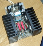
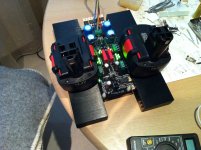
I have few pics of mine as well. I've run it for half of an hour with 3R css resistors. What could I say, it was about 60c on this tiny toroid (just confirmed what Andrew said dozen of pages ago), 80c on CSS Rs, 75c on mosfets, 60c on MUR860s, 55c on the sinks. I'll get some M2 bolts to attach mosfets properly on this week and continue with preliminary burnings tests
Last pic shows the layout, please let me know if it's decent enough?! toroid will be replaced with something <80mm width & <55mm height (probably should be some custom narrow 80VA or 65VA r-core transformer).
Yet another thing to clarify
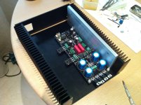
As my goal is >=1A (I need >65VA transformer), would it be good to add additional solid 10mm aluminum plates to the heatsinks (as on pic 2) or perhaps to add a solid 10x160x250mm plate to the bottom? What I want is to win some several hundreds mA more to burn it even harder dimkasta
very nice chassis!
Attachments
Last edited:
After you will have the Mosfets properly bolted on sinks and final CCS current of choice, we will know the temperatures on sinks and Mosfet cases you will measure. From there we will be able to judge if they will be safe conditions in the long run or you will need to upgrade thermals either for pads or for extra metal.
*See to give the MUR diodes some contact to the metal floor if not bothering to bolt and insulate individually which can be PITA. An insulating strip running their tabs and a bracket pressing them all together on their plastic cases maybe. Matters at the current level you aim at.
*See to give the MUR diodes some contact to the metal floor if not bothering to bolt and insulate individually which can be PITA.
thanks! is it safe to keep them above 60c? Anyway I was planning to attach them to the chassis.
How much voltage you got now across the current setting resistors on average?
it's 2.02 &1.85vdc with 2 x 6R per rail. So it's >600mA now. Not sure how much more could I get from the trafo as it's already on the edge to my understanding
I'll assemble the bottom lid and heatsinks and make the proper measurements. Will see then how far could I go.
- Home
- Source & Line
- Analog Line Level
- Salas hotrodded blue DCB1 build