Danzup,
please - as I am dumb in coding so far - what code has to be added in order to add one or two more inputs - could you advise? Apart from changing the "case" selection, any other definition?
Thanks!
Say for which firmware do you want to do modification and I will show you how .
In post #25, the 8515-PGA2310, +31.5 dB version...
Thanks!
Hey, danzup! Did you forget about me?

Sooory , been a little busy right now .Hey, danzup! Did you forget about me?
Here the code modified :
Attachments
If Inp_sel = 32 Then
Lcd "Aux2 selected"
End If
If Inp_sel = 32 Then
Lcd "Aux3 selected"
I assume it's a mistake here, should be 64 for Aux3, isn't?
Yes , I was in hurry !
Hi, Danzup! Hope you still attend this thread from time to time.
I have a question - is it possible to implement encoder in Project Nr.2 (8515+PGA2310)? What has to be done to make it so? On the PCB layout you provided - there is a connection for encoder foreseen, but there's nothing on the schematic. I am especially curious about the code...
Thanks!
I have a question - is it possible to implement encoder in Project Nr.2 (8515+PGA2310)? What has to be done to make it so? On the PCB layout you provided - there is a connection for encoder foreseen, but there's nothing on the schematic. I am especially curious about the code...
Thanks!
Yes . I will post the code in few days : must look where I have saved this variant of software.Hi, Danzup! Hope you still attend this thread from time to time.
I have a question - is it possible to implement encoder in Project Nr.2 (8515+PGA2310)? What has to be done to make it so? On the PCB layout you provided - there is a connection for encoder foreseen, but there's nothing on the schematic. I am especially curious about the code...
Thanks!
Sorry, i forget to delete group-buy. What i mean is the source code r-2r / shunt volume controller LED/LCD (ATM16_SHUNT_R_2R_LCD_V1.bas) not the PCB.
Thanks
That one not posting for now .
Maybe sometime in the future ....
I will see .
That one not posting for now .
Maybe sometime in the future ....
I will see .
I will wait. I want to know the function for Xrel0 and Jp1
Thank
I will wait. I want to know the function for Xrel0 and Jp1
Thank
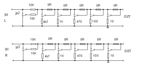
Xrel0 :
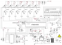
- for SS R2R/shunt firmware those are the lines for LED and Power relay for amplifier like in pictures 1
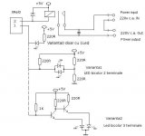
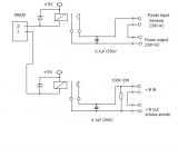
- for tube amplifier there is another firmware and like in pictures 2 where the anode +B voltage are connected after some wait (about 100 sec) and on standby this is disconnected first then the filaments power after 1 minutes (named in pictures Power in/out)
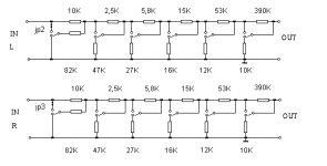
JP1 is for uC Atmega16 to know which resistor have you solder : R/2R values or Shunt values , as I said before for r/2R there are 64 steps for shunt only 32 steps .
check pictures 3 and 4
Attachments
Last edited:
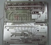
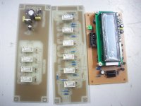
At first i want to build smd version from Vicol, this my PCB
, but i can't find some component, so i make another PCB without smd part.
I just test the control board, and it work. Thats it for now.
, but i can't find some component, so i make another PCB without smd part.
I just test the control board, and it work. Thats it for now.
Attachments
Last edited:
At first i want to build smd version from Vicol, this my PCB
, but i can't find some component, so i make another PCB without smd part.
I just test the control board, and it work. Thats it for now.
Congratulation for your pcb , looks so professional made !
- Home
- Source & Line
- Analog Line Level
- Yet another Volume controlers and source selections