hum problem
Hi, everyone. I finally finished building my ZV7R. But I have one problem, hum.
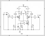
As you see in the attached schematics, I connected minus input to the ground and I inserted 10k pot (for volume) between plus input and C1 since I would like to use this as unbalanced operation. But hum comes out when I increase volume level. So I removed pot4, but still hum comes out. Next, I disconnected minus input and ground (balanced operation?) then the hum didn�ft come out. The input is open.
How should I connect minus input and ground for unbalanced operation? And how should I put pot4 for volume control? Please help me.
Kaz
Hi, everyone. I finally finished building my ZV7R. But I have one problem, hum.
As you see in the attached schematics, I connected minus input to the ground and I inserted 10k pot (for volume) between plus input and C1 since I would like to use this as unbalanced operation. But hum comes out when I increase volume level. So I removed pot4, but still hum comes out. Next, I disconnected minus input and ground (balanced operation?) then the hum didn�ft come out. The input is open.
How should I connect minus input and ground for unbalanced operation? And how should I put pot4 for volume control? Please help me.
Kaz
Attachments
 That would mean you need a dual pot for volume control. One on the - input to gnd also. And a small R to gnd on the - input to simulate your source R also...
your could fabricate a phase splitter...
Quoting the author: "A transistor amplifier can be configured to act as a phase splitter. C1 is the input signal coupling capacitor and couples the input signal to the base of Q1. R1 develops the input signal. R2 and R3 develop the output signals. R2 and R3 are equal resistances to provide equal amplitude output signals. C2 and C3 couple the output signals to the next stage. R4 is used to provide proper bias for the base of Q1. This phase splitter is actually a single transistor combining the qualities of the common-emitter and common-collector configurations. The output signals are equal in amplitude of the input signal, but are 180º out of phase from each other."
http://www.tpub.com/content/neets/14180/css/14180_40.htm
John")
Quoting the author: "A transistor amplifier can be configured to act as a phase splitter. C1 is the input signal coupling capacitor and couples the input signal to the base of Q1. R1 develops the input signal. R2 and R3 develop the output signals. R2 and R3 are equal resistances to provide equal amplitude output signals. C2 and C3 couple the output signals to the next stage. R4 is used to provide proper bias for the base of Q1. This phase splitter is actually a single transistor combining the qualities of the common-emitter and common-collector configurations. The output signals are equal in amplitude of the input signal, but are 180º out of phase from each other."
http://www.tpub.com/content/neets/14180/css/14180_40.htm
John
Attachments
Re: your could fabricate a phase splitter...
???
carpenter said:Quoting the author: "A transistor amplifier can be configured to act as a phase splitter. C1 is the input signal coupling capacitor and couples the input signal to the base of Q1. R1 develops the input signal. R2 and R3 develop the output signals. R2 and R3 are equal resistances to provide equal amplitude output signals. C2 and C3 couple the output signals to the next stage. R4 is used to provide proper bias for the base of Q1. This phase splitter is actually a single transistor combining the qualities of the common-emitter and common-collector configurations. The output signals are equal in amplitude of the input signal, but are 180º out of phase from each other."
http://www.tpub.com/content/neets/14180/css/14180_40.htm
John
???
carpenter said:Hi Choky,
I was pondering a way to convert a single-ended input into a balanced input signal for the ZV7.
John
I know.....but simetry is ,say,questionable .........at least on upper freq.....
read JLH and PLH papers
or I'm wrong........

 Your right
hum problem
Hi, every one. Thanks for the reply.
First of all, sorry, I made a mistake with my schemaics. The pot4 and C1 position is opposite. Plus input-pot4-C1 is correct.
I did the same connection for my mini son of zen and ZV6, but I had no problem. ( or I just couldn't recognized because the max output power is less than 1W) Are these such different? Anyway, I will try dual pot for both inputs tonight.

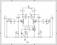
Hi, I have just tried to use two pots for both inputs like the attached schematics.
When the both inputs are open (balanced operation) the hum didn�ft come out even the full volume. But if the minus input is grounded (unbalanced operation) the hum did come out but it seems better than single pot case.
I think ZV7R and other Zen amplifier, say, first watt F1 have basically the same construction. So I�fm curious why F1 can do the unbalanced operation by simply plugging short pin into the minus and ground while ZV7R can�ft.
Attachments
salam-kaz, Right, but also there is a source impeadance to both inputs that is not balanced in that case. In the case of both inputs being open, you have infinate source impeadance. They are balanced. However, say for instance you are driving your + input with a 50 ohm signal generator. I believe ideally, you should have a 50 ohm resistor terminating the - input to ground also.
Another important consideration is, where are you actually connecting the -input ground? If it is in an area of high current, you could be picking up the hum as a voltage drop from that area. These things can be tricky...
Another important consideration is, where are you actually connecting the -input ground? If it is in an area of high current, you could be picking up the hum as a voltage drop from that area. These things can be tricky...
salam-kaz said:But if the minus input is grounded (unbalanced operation) the hum did come out
As you have the pot to the minus input,
you may leave the nimus input open
because the -input is already connected to the gnd through the pot
If so, the both +/- mosfet gates would see the same resistance
to the ground (hum source?)
Hope you will solve it soon
Hi Flg_san and Babowana_san. Thank you for the advice.
Kaz
Then, why the F1 doesn�ft have to adjust impedance ? Because the F1 has 221 ohm and 1M ohm resister after the input? Also, how does the F1 connect to an unbalanced source via volume?I believe ideally, you should have a 50 ohm resistor terminating the - input to ground also.
Does this mean ground loop problem? I tried many cases including �gstar ground�h but no improvement has seen yet.If it is in an area of high current, you could be picking up the hum as a voltage drop from that area.
Kaz
Babowana_san. Thank you for the advice.
I am currently using 4.7uF and I have 3.3uF and 1uF here now. I�fll try these, hopefully today.
Does this mean to prevent parasitic oscillation of Q3?
And also, thank you for visiting my website.
Recently I am too lazy to update English version.
I also visit your website. It�fs wonderful!
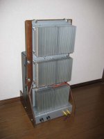
Attached picture is my ZV7R. PSU is separated.
This might be very unusual style.
Kaz
I am currently using 4.7uF and I have 3.3uF and 1uF here now. I�fll try these, hopefully today.
Does this mean to prevent parasitic oscillation of Q3?
And also, thank you for visiting my website.
Recently I am too lazy to update English version.
I also visit your website. It�fs wonderful!
Attached picture is my ZV7R. PSU is separated.
This might be very unusual style.
Kaz
Attachments
salam-kaz said:.......
Attached picture is my ZV7R. PSU is separated.
This might be very unusual style.
Kaz
ugly!

- Status
- This old topic is closed. If you want to reopen this topic, contact a moderator using the "Report Post" button.
- Home
- Amplifiers
- Pass Labs
- ZV7R: Question from beginner