I once biamped two FH1 with the quacky PV horns on top to a pair of 18" RJ - I preferred one K15 on organ - you know my fetishes - hehehe - I have liked FH1 with 511/K55V/APT150 but preferred a K12 with K-tube on top for an intimate sound - those slit vents from 1956 onwards distort crazy with sine but for music usually don't hurt things
we know the K's don't go deep, have cavity reflections, but sometimes are fun - are you going to boost at ~fb?
what would you expect from this little horn vs a stock Belle type? I would add some sort of funky sub http://usr.audioasylum.com/images/2/21168/2Bwith_reflector.gif
we know the K's don't go deep, have cavity reflections, but sometimes are fun - are you going to boost at ~fb?
what would you expect from this little horn vs a stock Belle type? I would add some sort of funky sub http://usr.audioasylum.com/images/2/21168/2Bwith_reflector.gif
Last edited:
Testing time
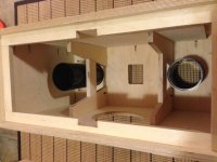
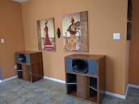
I got one of these monsters set up in room yesterday with the assistance of fellow audio lunatic and serial naysayer, kenpeter . Crossover is via minidsp . I didn't have the patience to set up my tube amp for the tweaking phase of this project so I employed a (very solid) solid state amp,.. the old mcintosh mc2100, as a test amp.
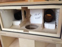
In the last pic, I tweaked the internal volume using styrofoam scraps (about 0.7 cuft of it altogether)
I got one of these monsters set up in room yesterday with the assistance of fellow audio lunatic and serial naysayer, kenpeter . Crossover is via minidsp . I didn't have the patience to set up my tube amp for the tweaking phase of this project so I employed a (very solid) solid state amp,.. the old mcintosh mc2100, as a test amp.
In the last pic, I tweaked the internal volume using styrofoam scraps (about 0.7 cuft of it altogether)
Attachments

Last edited:
Impressions:
Mid-High : The Faital Pro HF146 on the eightennsound XT1464 waveguide is a real gem of a combination . Goes down to 500 - 550 Hz with no audible artifacts (for home listening purposes). KenPeter thought it sounded better at 700 Hz, .. to me personally, .. not that big a difference. Enrn though it is a CD waveguide, the XT1464 doesn't need a lot of CD equalization, if any . It does benefit a bit from some CD EQ, .. but in someways, I prefer the uncompensated "full / warm/ slightly rolled off sound). FWIW, I've heard other CD waveguides that absolutely needed it. This one, not so much.
Bass: Well, to be honest, I'm not completely blown away by the ported lascala mod. I could be doing something wrong or haven't dialed things in yet (still playing with EQ and other things). The ports do work, .. so kudos to djk for that. I listened to some test tones and made mental notes of the SPL. I seem to get bass down to about 35 Hz - which is good, and the quality of the bass is "dry" - a horn bass characteristics. But some tracks (hip-hop / EDM) just sound weak. Acoustic bass on the other hand is just right. But overall, I feel I'm missing some "slam" or "punch", .. for lack of a better word, .. which is what I expected to achieve with this (mid)bass horn.
I'm not done EQ'ing and haven't taken a single SPL trace yet so perhaps there is something I'm missing. I'll describe the basis for my bass horn calculations and tweaking next.
From a few pages back, .. here the basis for a hybrid reflex-horn alignment.
http://www.diyaudio.com/forums/subw...es-variation-belle-klipsch-6.html#post4313813
For my build,
I estimate the net volume of the bass horn rear chamber (after subtracting driver volume) is 3948 in3
Likewise, the net volume of the top cabinet (after subtracting the volume for 2 ports and the waveguide) is about 5031 in3
Therefore the total volume when combined = 3948 + 5031 = 8979 in3 = 147 l = 5.2 cu ft
Here is an impedance sweep with this volume and the (2 x 4.5" DIA) ports extended to 9"
Attachments
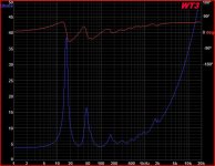
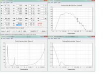
And here is another WT3 impedance sweep with the rear chamber reduced by about 0.7 cuft (using styrofoam scrap) and the ports reduced to their minimum length (7.5"). Not that the tuning point (the minima of the curve) has increased in frequency somewhat.
I didn't have any more properly sized pieces or else I would have tried to reduce the volume even more. I'm considering using foam insulation board in my next experiment to reduce volume.
I didn't have any more properly sized pieces or else I would have tried to reduce the volume even more. I'm considering using foam insulation board in my next experiment to reduce volume.
Attachments
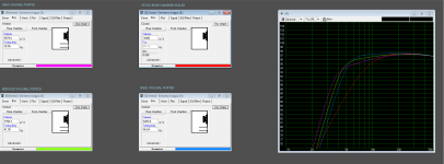
A summary of DJK's tuning instructions:
1. Identify the sealed volume for a Bessel max-flat alignment (Q = 0.577). In my case, that works out to about 6283 in3 .
2. Port this volume to an S4 . I coudn't find enough junk to reduce the volume to 6283 in3 so I ran two tests (one with the original volume of 8979 in3 ported, and another with 7768 in3 ported) .
3. Add a peaking high pass filter just below the porting frequency
4. Boost the bass at the porting frequency
Here's a screenshot of my simulation results . @DJK, I'd appreciate it if you could tell me if I'm on the right path here. From the curves, it looks like there's something to be gained by reducing the back chamber size by another 0.3 to 0.5 cu ft
Tomorrow or Monday, I will try and post my minidsp filters determined "by ear" . Likewise for the response curves.
Attachments
Referring to the image in the last post , I've tested configurations 4 and 6. Configuration 3 might be the one to beat. Thoughts ??
How does the measured impedance curve compare to the one from the HornResp sim? That IMO is the first place to start. Exporting the data and using Excel or something similar to compare the two curves may be enlightening. I've got a spreadsheet that I use just for that purpose, as I believe comparing the impedance curves is actually the best place to start when comparing a built alignment to its sim.
I don't suggest using WinISD or another simple box modelling tool is a sim tool for your build - it's not going to show the impact of the horn section of the build on the frequency response curve or the impedance curve.
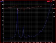
Here we go, .. they pretty much match the WT3 measurements (apart from the absolute value of the impedance peaks) . Looks like some boost in the 40 to 100 Hz is needed (or some cut above 100 Hz)
Attachments
Here we go, .. they pretty much match the WT3 measurements (apart from the absolute value of the impedance peaks) . Looks like some boost in the 40 to 100 Hz is needed (or some cut above 100 Hz)
Actually there's a minor blip at 80 Hz (panel flex?) and a noticeable peak at 150 Hz. The latter suggests that there may be a detail about your build that is missing from the sim. Best to overlay the two curves - that way the differences really jump out and become very noticeable.
Actually there's a minor blip at 80 Hz (panel flex?) and a noticeable peak at 150 Hz. The latter suggests that there may be a detail about your build that is missing from the sim. Best to overlay the two curves - that way the differences really jump out and become very noticeable.
The 150 Hz peak might be related to a 1/4 wave resonance between the parallel top and bottom surfaces (about 21 inches)
The other blip is related to sealing. I seem to recall it much much worse before I clamped the front down. I should probably clamp the rear down too. There is a bit more bracing to be done before I'm completely done (interior of the doghouse + I would like to add at least 1/8 to 1/4" to the outside rear of the horn and top chamber cabinets. This is an exercise in overkill
")
Thanks !!
Last edited:
The 150 Hz peak might be related to a 1/4 wave resonance between the parallel top and bottom surfaces (about 21 inches)
That would be unusual. I haven't seen a similar resonance show up in my measurements, particularly at that level. The magnitude of the resonance suggests that it has something to do with a fundamental component of the horn, rather than panel geometry.
apply ~+6dB @33-35 - how much bass might a ported mod tuned ~35 adding 2CF to the rear chamber modify the bass situation in my FH1? - do you have an 8ft ceiling? for a new toy I'm considering RCA-Fan's 70HZ horn but blending it to a sub is unknown
An externally hosted image should be here but it was not working when we last tested it.
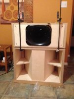
Getting there ... Need to hookup the amps , tune the crossovers and build some fabric grills to cover the butt-ugly waveguide..
With a young infant in the house, I bought a couple of relatively inexpensive"lightweight" amps as I don't want to risk the damage to infant or amp with the 2A3 amp or the boat-anchor mcintosh MC2100
Mid-High : https://www.amazon.com/Gemtune-APPJ-PA1501A-amplifier-6AD10/dp/B00X5ECQ4Q
Bass: https://www.amazon.com/SMSL-Digital-Amplifier-Coaxial-Optical/dp/B019SLU25O
Attachments
Those speakers look AWESOME!
Thanks - and I'm not done with them cosmetically.
Next, the fun begins.
1. Measurement of the bass and CD horns. The bass module is currently sealed. If I open up the access panel separating the back chamber of the bass horn and the mid-high enclosure, this enclosure transforms to a ported / horn hybrid.
I'll try and post comparative measurements.
2. After I have a change to take measurements and see what I prefer, I'll start tweaking the crossover - a regular minidsp for now (might upgrade later)/ Need to see if a sub is needed or desired.
So, without even taking measurements - I'm contemplating a couple of changes
This is the current chain:
Source : cheap intel atom based laptop PC or raspberry pi
XOver : minidsp 2x4
Mid-Hi : amp - GemTube APPJ-PA1501A compactron based mini tube amp : https://www.amazon.com/Gemtune-APPJ-PA1501A-amplifier-6AD10/dp/B00X5ECQ4Q
Bass amp: SMSL Q5 pro amp : https://www.amazon.com/SMSL-Q5-Pro-silver-Component/dp/B017W139EI
Issue : The tube amp has A BIT of 120 Hz (power supply) hum - specifically in the left channel. I swapped tubes between channels but the sound stayed in the left channel so I believe it's internal to the circuitry.
Option 1: return the amp - I've already generated an RMA in case this is the course I chose
Option 2: Use a first order protection capacitor on the compression driver - constant directivity horn combo. This can have 3 benefits and 1 drawback
Benefits:
a. Assuming a reasonable choice of crossover frequency, I should be able to filter out most of the hum
b. Protect the compression driver from turn on pops or accidents (though this tube amp turns on without wierd noises and is also low power - 3 WPC)
c. Assuming a reasonable choice of crossover frequency, I should be able to achieve some constant directivity compensation at the same time.
Drawback: Using an inline protection capacitor will affect the phase AT the passive crossover point ,, further compounded by the proposed use of an active crossover stacked on top of this. Regardless, I'm not sure if I should be using a protection cap tuned to crossover 1 octave above or below the desired active crossover point ?
Edit: see link : http://www.audioheritage.org/vbulle...n-active-setup&p=305120&viewfull=1#post305120
Any other thoughts / options ? I'm familiar with many of the concepts of crossover design but might need some help with this one
I'm open to all ideas - including (gasp) pure passive crossover
Last edited:
Update. Tried a 100 uF NPE protection cap to see if it would filter out the hum I heard. No luck. So I guess the tube amp will ship back tomorrow.
For the time being, since I have no plans to bring out either the boat anchor mcintosh or the boat anchor DIY 2A3 tube amp (neither of which are child safe or mountable on a wall shelf), I guess I'll purchase another SMSL q5 pro class D amp (at least it's dead silent)
For the time being, since I have no plans to bring out either the boat anchor mcintosh or the boat anchor DIY 2A3 tube amp (neither of which are child safe or mountable on a wall shelf), I guess I'll purchase another SMSL q5 pro class D amp (at least it's dead silent)
Attachments
Last edited:
- Status
- This old topic is closed. If you want to reopen this topic, contact a moderator using the "Report Post" button.
- Home
- Loudspeakers
- Multi-Way
- zobsky contemplates a variation on the belle klipsch