Paralleling JFETs does not increase gain. You just end up with four times the transconductance feeding into a quarter of the drain resistance, so exactly the same gain. The only advantages are a reduction in noise and a reduction in output impedance.
There is no point in specifying (and attempting to achieve) component values to 5 significant figures if you only know about 2 significant figures on the initial resistance of the network (47k + 0-2k).
There is no point in specifying (and attempting to achieve) component values to 5 significant figures if you only know about 2 significant figures on the initial resistance of the network (47k + 0-2k).
PRR said:I really do not understand 2KR1 R11 bleeding heavy DC current and lots of audio to ground, throwing-away gain which is usually precious in MM preamp work.
I think PRR knows that. His "I do not understand" may be polite code for 'I suspect you do not understand, but I am open to receiving a coherent explanation''.andyr said:The res in that position after each JFET quad, shunting to ground, is what influences the gain.
Paralleling JFETs does not increase gain. You just end up with four times the transconductance feeding into a quarter of the drain resistance, so exactly the same gain. The only advantages are a reduction in noise and a reduction in output impedance.
Having built the same circuit with a pair of JFETs and then a quad ... I can assure you that parallelling JFETs does increase the gain - in my circuit, anyway. The explanation I was given is because the transconductance figure influences the gain - so when it is doubled (compared to a pair) ... the gain (approximately) doubles.
There is no point in specifying (and attempting to achieve) component values to 5 significant figures if you only know about 2 significant figures on the initial resistance of the network (47k + 0-2k).
True.

I think PRR knows that. His "I do not understand" may be polite code for 'I suspect you do not understand, but I am open to receiving a coherent explanation''.
Your assumption of PRR's polite code is correct!
I seek to be educated.
Andy
You are not comparing like with like. To a first approximation, twice the number of JFETs means twice the quiescent current which means half the drain resistor so the gain stays the same.andyr said:Having built the same circuit with a pair of JFETs and then a quad ... I can assure you that parallelling JFETs does increase the gain - in my circuit, anyway. The explanation I was given is because the transconductance figure influences the gain - so when it is doubled (compared to a pair) ... the gain (approximately) doubles.
You could go the other way and say that doubling the drain resistor increases the gain. True, but again not comparing like with like as increasing the resistor changes the drain voltage and raises the output impedance.
PRR is correct R1 and R11 should be eliminated they lower the gain but also drastically increase the distortion. Look at the Original Pearl article I wrote. This is a more complicated version of that and could work well with some tweaking.
Thanks, Wayne.
Have managed to find both your Pearl articles - so will have a good read over the w/e.
Regards,
Andy
> Paralleling JFETs does not increase gain.
It "can".
Gm goes roughly as square-root of current. Lower the current, increase the resistance(s), gain goes up about as square-root of current going down.
If the new lower current, high resistance, will not drive the load, parallel a bunch.
Pick a current. Say 8mA. Say you find gain of 10. Now use four devices at 2mA each. Still 8mA total, use the same load resistance. Each device at 1/4 current will give 1/2 the Gm. Four devices makes 4*(1/2) or 2X the Gm of the one device plan, gain of 20.
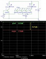
In the sim, I set one FET at 12mA with 24V supply and 1K load. Then I quadded four of the same FET and fiddled the bias to get nearly the same total current (1/4th in each device), same supply and load.
While frequency sweep is not the point, that is the easiest way for my sim to present small-signal gain in dB.
The square-root rule of thumb predicts 2X or 6dB change of gain.
In fact it plots 5.7dB which is close enough for a rule of thumb.
In-in fact-fact, I missed the 12mA goal on the quad. Using 11.2mA the RoT predicts .... 5.7dB. Trimming for equal currents and Vds it sims 6.06dB (s/b 6.02dB). Scary.
Of course if gain is the only goal, 2X gain for 4X cost is a poor bargain. *Cascading* the four devices as a 4-stage amplifier gives 477X or 53dB the gain. And gives you three places to nibble-out your RIAA curve. Perhaps 20dB at a time instead of 40dB in one great chunk.
It "can".
Gm goes roughly as square-root of current. Lower the current, increase the resistance(s), gain goes up about as square-root of current going down.
If the new lower current, high resistance, will not drive the load, parallel a bunch.
Pick a current. Say 8mA. Say you find gain of 10. Now use four devices at 2mA each. Still 8mA total, use the same load resistance. Each device at 1/4 current will give 1/2 the Gm. Four devices makes 4*(1/2) or 2X the Gm of the one device plan, gain of 20.
In the sim, I set one FET at 12mA with 24V supply and 1K load. Then I quadded four of the same FET and fiddled the bias to get nearly the same total current (1/4th in each device), same supply and load.
While frequency sweep is not the point, that is the easiest way for my sim to present small-signal gain in dB.
The square-root rule of thumb predicts 2X or 6dB change of gain.
In fact it plots 5.7dB which is close enough for a rule of thumb.
In-in fact-fact, I missed the 12mA goal on the quad. Using 11.2mA the RoT predicts .... 5.7dB. Trimming for equal currents and Vds it sims 6.06dB (s/b 6.02dB). Scary.
Of course if gain is the only goal, 2X gain for 4X cost is a poor bargain. *Cascading* the four devices as a 4-stage amplifier gives 477X or 53dB the gain. And gives you three places to nibble-out your RIAA curve. Perhaps 20dB at a time instead of 40dB in one great chunk.
Attachments
>
Paralleling JFETs does not increase gain.
It "can".
Gm goes roughly as square-root of current. Lower the current, increase the resistance(s), gain goes up about as square-root of current going down.
If the new lower current, high resistance, will not drive the load, parallel a bunch.
Pick a current. Say 8mA. Say you find gain of 10. Now use four devices at 2mA each. Still 8mA total, use the same load resistance. Each device at 1/4 current will give 1/2 the Gm. Four devices makes 4*(1/2) or 2X the Gm of the one device plan, gain of 20.
In the sim, I set one FET at 12mA with 24V supply and 1K load. Then I quadded four of the same FET and fiddled the bias to get nearly the same total current (1/4th in each device), same supply and load.
While frequency sweep is not the point, that is the easiest way for my sim to present small-signal gain in dB.
The square-root rule of thumb predicts 2X or 6dB change of gain.
In fact it plots 5.7dB which is close enough for a rule of thumb.
In-in fact-fact, I missed the 12mA goal on the quad. Using 11.2mA the RoT predicts .... 5.7dB. Trimming for equal currents and Vds it sims 6.06dB (s/b 6.02dB). Scary.
Of course if gain is the only goal, 2X gain for 4X cost is a poor bargain. *Cascading* the four devices as a 4-stage amplifier gives 477X or 53dB the gain. And gives you three places to nibble-out your RIAA curve. Perhaps 20dB at a time instead of 40dB in one great chunk.
Very interesting, PRR - I appreciate you spending the time to sim.
I can't understand one of your assumptions, though?
* you started off with "Pick a current. Say 8ma."
* then you compare its gain to a quad which has the same 8ma entering the quad - so shared across all 4 JFETs.
* (though actually in the sim, you used 12ma, not 8ma)
* why wouldn't you compare the single-FET gain against the gain of a quad where 8ma (or 12!) was going through each JFET?
* surely this is a direct comparison of the gain which results from using a quad of JFETs vs. a single JFET:
Andy
OK.PRR said:It "can".
You may reach a point of diminishing returns as the parasitic capacitances increase.
In that situation you get no increase in gain, as I explained in an earlier post - provided you are comparing like with like. Four JFETs into 2k gives the same gain as one JFET into 8k.andyr said:* why wouldn't you compare the single-FET gain against the gain of a quad where 8ma (or 12!) was going through each JFET?
OK.
In that situation you get no increase in gain, as I explained in an earlier post - provided you are comparing like with like. Four JFETs into 2k gives the same gain as one JFET into 8k.
Sorry - you've lost me, DF?
I was talking about the relative gain of:
* 1x JFET with 8ma running through it vs.
* 4x JFETs, each with 8ma running through them.
I didn't mention anything about different 'load' resistors? But I had the same load res (2K) in both instances.
Andy
If you want the same output swing then you have to change the load resistor.
It is obvious that 4xFET into 2k at 8mA each will give more gain than 1xFET at 8mA into 2k, but it will also give a very different drain voltage so you get different swing. Or it would need a very different supply rail voltage. You really must compare like with like, otherwise your statements are either meaningless or trivial.
Take your design. Use one FET, and make the resistor 8k. You get exactly the same gain, same output swing but more noise and higher output impedance (and lower input capacitance). So how has your four FETs boosted the gain?
If you want the same output swing then you have to change the load resistor.
It is obvious that 4xFET into 2k at 8mA each will give more gain than 1xFET at 8mA into 2k, but it will also give a very different drain voltage so you get different swing. Or it would need a very different supply rail voltage. You really must compare like with like, otherwise your statements are either meaningless or trivial.
Take your design. Use one FET, and make the resistor 8k. You get exactly the same gain, same output swing but more noise and higher output impedance (and lower input capacitance). So how has your four FETs boosted the gain?
It seems my thinking (an electronics numbie) is different to yours, DF.
I have 2 scenarios:
* 1x JFET - with 8ma running through it (actually, only about 5ma, for the JFETs I have chosen)
or
* 4x JFET - each with 8ma running through them (5ma).
I adjust the single Source resistor in each case, to give me the current I want - the whole point in my comparison is that both scenarios have the same current flowing through each JFET. As this seems to me to be the fair comparison, re. the gain delivered by a single ... or a quad of JFETs.
As you say, the 2 scenarios would deliver very different Drain voltages - except I have the ability to alter the CCS resistor, to ensure the Drain voltage in both cases is 12v.
This seems to me to be a fair way to compare the gain of a single JFET vs. the gain of 4x JFETs? IE. like-for-like ... the same current through each JFET and the same Drain voltage and the same 'load' res.
Andy
Where did a "CCS resistor" suddenly appear from?
Yes, it is true that using four FETs you can make a circuit which has more gain than a different circuit using one FET. You can also make a circuit with less gain or the same gain.
However, if you want the same quiescent current through each FET and the same output swing from the same supply rail then you need a smaller drain resistor so you end up with the same gain. As I showed, you can get the same gain from one FET and four times the resistance. PRR showed that you can get increased gain by reducing the current and raising the drain resistor. You can then get less noise and lower output impedance by putting a number of these in parallel - but the same gain.
You can almost always boost gain by increasing the circuit current draw, without adding extra devices.
...boost gain by increasing the circuit current draw...
That's brute force, and often misses.
In a resistor-loaded voltage amplifier, you can raise supply voltage (and load resistor), or *reduce* current (again with increased load resistor).
The reduced current / raised resistor does, ultimately, cut-off upper frequencies that you might want.
In AM radios, where >5KHz was bad, 12AX7-like tubes would be run with 470K plate resistors for a little more gain over most of the audio band (and less in the top two octaves). OTOH Fender moved from 220K-470K to 100K plate resistors and (in conjunction with other system changes) found ringing highs that defined Bakersfield sound and ultimately Rock.
Like I think you do, I tend to take the "engineering view". How much is the budget? I can't throw eight rocks under the bridge if the budget will only cover two rocks. If I draw more rocks I better know exactly how much better the bridge will be. Of course in DIY small-audio, rocks FETs and mA are not budget-breakers even in 25-bags.
- Status
- This old topic is closed. If you want to reopen this topic, contact a moderator using the "Report Post" button.
- Home
- Source & Line
- Analogue Source
- Zin of the 2nd stage of a JFET-based phono stage when a pair of JFETs is used?