DcibeL said:Wow, you're right Kevin, I opened up my Zhaolu 2.5A yesterday and the PCB layout of this DAC is atrocious. Looks like I have a lot of work ahead of me with a soldering iron and an exacto knife.
I notice in many places I see parts which are grounded to the ground plane on both the top and bottom of the board. That is, the part connects to a via which connects to ground on the top and bottom. What are your thoughts on this? Is there any gain to be had from removing one of these ground connections? I see many instances of this on all three boards (DAC, PSU, and analog).
Pretty shocking isn't it? In light of your question I think it is probably not a big issue to join the top and bottom planes together at components providing that big currents are not flowing across the via. The key is to remove any high current loops like the transformer center tap I mentioned in a previous post. In theory it would be better to connect to one plane or the other, but in practice as long as current isn't flowing across the via it probably doesn't matter too much. Try it and see...

One of the bad things about these thermal vias is that the size of the conductors is tiny - I've had significant gains by scraping to bare copper and soldering wire across the via to the adjoining plane.
Member
Joined 2003
Kevin,
I removed CON1, cut the traces around pin 4 top and botton, cut the trace between pin4 and the - side of the 2200uF cap, then ran a wire from the - side of this cap to the mecca point, then out CON1 back.
However, I also see hairlike traces around the - pin of the cap. Should I cut these also?
These little traces seem to be everywhere, all over the board on various pins. It sounds like they should not be there at all, per your posts.
Another question on the DAC board, should I replace the standoffs on the DAC board with teflon standoffs and just make a single ground plane to the chassis? Would that be a worthwhile idea, in your opinion?
Thanks,
Bob
BobM said:Kevin,
I removed CON1, cut the traces around pin 4 top and botton, cut the trace between pin4 and the - side of the 2200uF cap, then ran a wire from the - side of this cap to the mecca point, then out CON1 back.
However, I also see hairlike traces around the - pin of the cap. Should I cut these also?
These little traces seem to be everywhere, all over the board on various pins. It sounds like they should not be there at all, per your posts.
Another question on the DAC board, should I replace the standoffs on the DAC board with teflon standoffs and just make a single ground plane to the chassis? Would that be a worthwhile idea, in your opinion?
Thanks,
Bob
Hi Bob,
No don't cut those little traces around the ground pin of that cap, otherwise you sever it from the circuit it is meant to feed and then if you are lucky it will find a more convoluted way to complete the circuit path.
No actually I wouldn't recommend replacing those metal standoffs with teflon insulated posts because in some cases that is the only low impedance ground reference for the circuit in question. This approach is actually considered good practice in the digital and rf world and changing this aspect of the design without careful study could cause all sorts of unforeseen problems. You could try it of course, keeping the original pieces in case it doesn't work well, and you could also try the copper foil which does considerably improve the integrity of the grounds through the chassis. Incidentally the audio board is isolated from the chassis so ground loops generating hum shouldn't be a big issue.
I do recommend beefing up the connections to the ground plane particularly on those goofy grounded traces as they are pretty small and don't provide a very low impedance connection to the via. I recommend doing this at the output capacitor for each of the analog supply voltages, and possibly anywhere else you feel motivated.
I had hoped my next lot of mod parts would be here today as it is snowing like the dickens, and I hoped to do some more mods this week-end.
Another not so minor update:
I just replaced the two black smd 100uF/10V tantalum caps adjacent to the dac on the analog ground plane - they are the only ones near the audio output to the analog board.
Analog Devices recommends 10uF caps, Zhaolu used 100uF.. I replaced these with 47uF/63V Silmics recently removed from my Sony SCD-777ES. These are very good quality caps and the effect they had on the Zhaolu's sound quality was immediately noticeable.
Of course you won't be surprised to hear that the Sony still wins this round, and on serious listening the differences aren't terribly subtle, but things have converged to the point where I can describe some of the differences at least.
I am listening to Elvis Costello's Il Sogno recorded a few years ago by the LSO. It's a wonderful work and a shock to me on several levels - I was never a big fan of his new wave stuff.
The Sony sounds much bigger, and fuller, more dynamic, more analog like, with unbelievable bottom end authority. The sound stage is both wider, and deeper. It is both cleaner, easier to listen to and far more detailed. There is a real sense of vibrancy and immediacy to the music and this is where the Zhaolu really hurts the music - it's just not there at all, sucked dry by comparison. The Sony even on good cds starts to sound almost analog particularly with the VC24 filter set to mode 1. (Not comparing to SACD as that is in another ball park altogether.) The Zhaolu has gained some poise and doesn't fall completely apart on complex material, but the acoustical space is small and the stage is shallow, instruments lack texture, and dimension. There is still a lot missing, but the errors now seem to be more of omission than commission, it isn't adding the layers of grunge it did before, and it does improve significantly as it warms up. I would say if I did not have the Sony as a point of comparison I would be bowled over by the level of improvement so far - it isn't subtle, and on reflection I find I can almost actually listen to it again. (Unfortunately not quite as close as I would hope..)
Yet another in a long series of interminable updates.
I just jumpered out the caps on the input of the analog board, and while I have not completely decided I think it might be sounding slightly better on the same material I previously used.
Still all previous comments apply plus I have noticed that it doesn't handle percussive attacks that cleanly..
Still it might be better, decide for yourself - that's what it is all about..
Still more updates, these on the power board.
Replaced both 1000uF/16V with 1000uF Nichicon Muse.
Low voltage digital supply: Isolated dip based bridge rectifier negative terminal from ground plane and soldered wire from negative rectifier terminal to negative terminal of cap.. Made solid connection to ground plane here. (To do this I cut around the entire pad around the negative terminal and removed the pad, bottom side I cut the 4 little traces around the via.)
Analog power ground at connector scraped away solder mask and added small piece of wire soldered to ground plane.
Add small piece of braid from adjoining plane to any stand-off pad connected to that ground.
Some improvements noted. A little less mechanical sounding, and the subjective noise floor has dropped considerably.
Kevin,
Thanks for all your reports and updates. I've done a number of your ground scheme changes, as well as the relay bypass. It is hard to tell the exact change between before and after, but I can say that I definitely hear a drop in the noise floor. Blacker backgrounds for sure and a much better sense of space, especially depth of soundstage, that wasn't as prominent before. The Zhaolu always impressed me with the width of its soundstage, but it was a bit shallow - no more.
I am using the 2.5C with the CS4398 DAC chip. Looking at the specs at Digikey it looks like ot also calls for 10uF caps at pin 7 and 22 (VD and VA). It's hard to trace the board with such tiny traces but it looks like mine also has the 100uF 10V surface mount caps on it. I have not had much luck with surface mount component modding in the past, so I'm prone to leaving these alone for now instead of trying to replace them with something else, unless the improvement is dramatic.
I'm looking forward to your other findings.
Enjoy,
Bob
Hi Bob,
I think you should try to replace those 100uF/10V tantalums on the reference and analog supply pins - it does make quite a difference. I changed these from Silmic to Black Gate standard type 47uF/25V.
I also replaced all of the resistors in the input circuitry of the analog board with Holco H4 1.02K (couldn't get 1K) - these are the older ones.
I also replaced one pair of 2K resistors with Holcos - there is another pair that are not necessary as they go from the output of the first stage to the relay I removed. (You don't need to remove this relay, and if you use the headphone amplifier I would upgrade them.)
I revised the power supply bypasses by removing all of the 46uF/16V caps on the analog board and one pair of the 1uF films - I installed the new Black Gates were the films had been because of the lead spacing was the same.
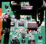
I have included a terrible picture of the mods to the audio board, the key at the input is to figure out how to bypass a bunch of traces.
The 100K resistors are not required.. On the inputs going to the inner pair of wires on the connector (the ones closest to the connector ground) I have added 2K resistors to make the input impedance symmetrical on the inverting and non-inverting inputs of the diff amp. I have deleted all of the input coupling caps.
The improvements overall are significant enough that I can now tell there is a difference between the Sony and the Media Server as sources - and the Sony wins here too, but the difference was not audible previous to these latest mods. The tonal balance is still leaner than the Sony, but the differences are somewhat less pronounced now. I doubt it will ever equal the Sony but it is much better sounding benchmarked against the Sony (SCD-777ES) than it was when I started.
I will turn my attention to the digital card shortly. I plan to upgrade the RCA jack and may or may not add an input transformer on a permanent basis. (I'll have to try it.) I am going to scrutinize this board for other issues, but because of the very small smd parts on this board I am probably not going to make a lot of changes. (I may replace some of the 10uF tantalums with Black Gates depending on where they are circuit wise.)
I think you should try to replace those 100uF/10V tantalums on the reference and analog supply pins - it does make quite a difference. I changed these from Silmic to Black Gate standard type 47uF/25V.
I also replaced all of the resistors in the input circuitry of the analog board with Holco H4 1.02K (couldn't get 1K) - these are the older ones.
I also replaced one pair of 2K resistors with Holcos - there is another pair that are not necessary as they go from the output of the first stage to the relay I removed. (You don't need to remove this relay, and if you use the headphone amplifier I would upgrade them.)
I revised the power supply bypasses by removing all of the 46uF/16V caps on the analog board and one pair of the 1uF films - I installed the new Black Gates were the films had been because of the lead spacing was the same.
I have included a terrible picture of the mods to the audio board, the key at the input is to figure out how to bypass a bunch of traces.
The 100K resistors are not required.. On the inputs going to the inner pair of wires on the connector (the ones closest to the connector ground) I have added 2K resistors to make the input impedance symmetrical on the inverting and non-inverting inputs of the diff amp. I have deleted all of the input coupling caps.
The improvements overall are significant enough that I can now tell there is a difference between the Sony and the Media Server as sources - and the Sony wins here too, but the difference was not audible previous to these latest mods. The tonal balance is still leaner than the Sony, but the differences are somewhat less pronounced now. I doubt it will ever equal the Sony but it is much better sounding benchmarked against the Sony (SCD-777ES) than it was when I started.
I will turn my attention to the digital card shortly. I plan to upgrade the RCA jack and may or may not add an input transformer on a permanent basis. (I'll have to try it.) I am going to scrutinize this board for other issues, but because of the very small smd parts on this board I am probably not going to make a lot of changes. (I may replace some of the 10uF tantalums with Black Gates depending on where they are circuit wise.)
Attachments
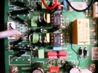
Here's a snapshot showing the Black Gates installed on the digital board, so far this is the only change to this board, but it makes a really major difference.
Basically bend the leads at right angles about 1/4 from the bottom of the cap, tin, and solder to pads. Check orientation such that both pads are reachable with your iron prior to cutting the leads.
Make sure you orient the caps correctly, the solid bar on tantalums is the positive terminal, through hole parts are usually marked on the negative side!
Without looking really closely at this board it does appear to be better laid out than the other two. Closer inspection will probably indicate a good number of changes are required here too.
Changes previously noted on the power supply board have a very large impact on the performance of the digital board however.
Attachments
Thanks again Kevin. It looks like you have essentially rebuilt the analogue output stage. 
If you haven't tried them yet I would like to reemphasize some op-amp choices the Paul Kap recommended. Try two OPA2107 op amps in that output stage for some beautiful Burr Brown style sound. If you want something more akin to a Benchmark then the LM4562's that some people like give the Zhaolu more openness and top end air, but a bit too much to my ears, personally. (I never really liked the Benchmark sound toat much)
I'll try and dig up some caps from my stash for the digital board and give it a try. That's for helping with the orientation of the SMD's - I would have guessed the line on them meant to opposite, like a regular cap.
Bob
Hi Bob,
I've tried a slew of different BB op-amps in this and several other dacs, oddly enough I don't really care for them. Not sure why, I try really hard to like them, but they are just a bit too smooth sometimes, real music doesn't sound that way.. At the moment I just happen to prefer the LM4562 to everything else to the extent that I pretty much indiscriminately stick it in everything, and then work on other parts of the circuit to fix what I hear..
Yes the analog board is pretty much completely rebuilt..
Now for the digital board..
Yes I have spent a few hours today working on that, and on the version I have (AD1852) I replaced the 10uF tantalum after the 22uH choke feeding the analog supply of the dac with a 47uF/25V BG. Some gains here. I also replaced the spdif rca with an isolated bnc, and reinforced all of the standoff ground connections on the bottom of the board with braid to the plane.
Incidentally as much as I hate to bring up the subject I can hear the difference between some of my various digital interconnects. I have 75 ohm bnc, prototype spdif cable with rca plugs and an Audio Alchemy DST (active balanced transceiver set up.) listed in order from worst to best. The sound with the prototype and DST cables is fuller and much less lean sounding, the DST wins overall. I know it makes no sense and I won't try to explain it, but the spdif input is sensitive to the whatever is connected to it. Incidentally it does not appear to be correctly terminated, but further investigation is required.
Frankly I am probably done at this point, while it still falls short of the Sony, it sounds so much better it is hard to imagine it is the same dac.
It has a big, expansive sound, the noise has dropped through the floor, the sound stage is neither as wide nor as deep as the Sony but again it is hugely improved. There is much more sense of space.
Bass on cellos, uprights, and electrics is much more palpable, you can feel it now, every note well delineated.
Performance with the server while not quite as good as the Sony as transport it is close enough to satisfy me.
Several hours of warm up are needed to hear it at its best.
One comment I will make is the Sony captures the emotion of the music and just does everything right by comparison. The Zhaolu gives you more than a hint, but I just don't get the goosebumps listening to it that the Sony gives me on very well recorded material.
I've tried a slew of different BB op-amps in this and several other dacs, oddly enough I don't really care for them. Not sure why, I try really hard to like them, but they are just a bit too smooth sometimes, real music doesn't sound that way..
At the moment I just happen to prefer the LM4562 to everything else to the extent that I pretty much indiscriminately stick it in everything, and then work on other parts of the circuit to fix what I hear.. Yes the analog board is pretty much completely rebuilt..
Now for the digital board..
Yes I have spent a few hours today working on that, and on the version I have (AD1852) I replaced the 10uF tantalum after the 22uH choke feeding the analog supply of the dac with a 47uF/25V BG. Some gains here. I also replaced the spdif rca with an isolated bnc, and reinforced all of the standoff ground connections on the bottom of the board with braid to the plane.
Incidentally as much as I hate to bring up the subject I can hear the difference between some of my various digital interconnects. I have 75 ohm bnc, prototype spdif cable with rca plugs and an Audio Alchemy DST (active balanced transceiver set up.) listed in order from worst to best. The sound with the prototype and DST cables is fuller and much less lean sounding, the DST wins overall. I know it makes no sense and I won't try to explain it, but the spdif input is sensitive to the whatever is connected to it. Incidentally it does not appear to be correctly terminated, but further investigation is required.
Frankly I am probably done at this point, while it still falls short of the Sony, it sounds so much better it is hard to imagine it is the same dac.
It has a big, expansive sound, the noise has dropped through the floor, the sound stage is neither as wide nor as deep as the Sony but again it is hugely improved. There is much more sense of space.
Bass on cellos, uprights, and electrics is much more palpable, you can feel it now, every note well delineated.
Performance with the server while not quite as good as the Sony as transport it is close enough to satisfy me.
Several hours of warm up are needed to hear it at its best.
One comment I will make is the Sony captures the emotion of the music and just does everything right by comparison. The Zhaolu gives you more than a hint, but I just don't get the goosebumps listening to it that the Sony gives me on very well recorded material.
Not having quite finished the planned mods I replaced the 16V supply output filter caps on the power board with the oft mentioned Black Gate 47uF (which despite previous posts are actually all 50V parts.) I removed both the Elna red bodied and black bodied caps from the regulator outputs. The Black Gates will fit nicely where to original black bodied Elnas were located. Incidentally this appears to help the sound in addition to all of the previous mods. (! Note: Overall capacitance on the outputs is reduced from about 250uF to 100uF with all of the changes to the power and audio boards - see the next paragraph!)
Something really important to note, while I did not trace out the power supply circuit in full detail I can say it is original to Zhaolu, and while I have heard of such an approach in my readings I can tell you it is most emphatically not based on the Jung or Sulzer designs. There are what appear to be several ring of two current sources, zener diodes are used I believe for level shifting, and the op-amp feedback loop is ac coupled to the output of the supplies as far as I can figure out. The dual op-amp is configured as inverting amplifiers, and is powered from the regulator outputs.
I checked it for stability and it is clean, but I would not make too many changes beyond what I have done as it might become unstable...
It does sound good...
Hi Guys,
I've been following your mods with interest. I have a 2.5C that I rolled opamps (LM4562, 2107 and a couple more that I've forgotten), replaced blocking caps and tried shorting them. It helped a lot and sounded great for the money but still wasn't at a level to compete with the best, IMHO.
I installed a Zapfilter. Installing a discrete output stage simply takes this up several levels in sound quality. Super black background, smooth and ultra detailed with exceptional clarity at all frequencies. It turned the Zhaolu 2.5C into a real keeper for me.
Ori favors the AD1852 version for his mods. I've not heard it but it gets great user reviews. I wanted to do my own and most had reported the CS4398 had better bass stock than the AD1852 so I went with the C version. If you want to turn the Zhaolu into a world class DAC, try a discrete output stage. Amazing sound quality for the investment, IMHO.
Jim
I installed a pulse transformer on the RCA digital input (Mouser part # PE-65612, all of $3.87). This brought the RCA input much closer to the good sound I am getting from the TOSLINK connection. There is definitely a problem with the RCA digital input on this DAC, because it should easily eclipse the TOSLINK. The pulse transformer evens the score, but I think more mods are needed in this critical area to bring it to where it should be.
Anyone have any ideas what else could be improved here, and how to go about it?
Thanks,
Bob
Anyone have any ideas what else could be improved here, and how to go about it?
Thanks,
Bob
BobM said:I installed a pulse transformer on the RCA digital input (Mouser part # PE-65612, all of $3.87). This brought the RCA input much closer to the good sound I am getting from the TOSLINK connection. There is definitely a problem with the RCA digital input on this DAC, because it should easily eclipse the TOSLINK. The pulse transformer evens the score, but I think more mods are needed in this critical area to bring it to where it should be.
Anyone have any ideas what else could be improved here, and how to go about it?
Thanks,
Bob
Hi Bob,
Outside of all the things I have addressed?

I will order one of those transformers, but in my case both sources have transformers on their outputs.
I did improve the digital grounding on the dac board with the addition of some braid to provide a lower impedance ground path to the chassis connections. The three caps I changed in the analog section of the dac board made a very big difference. FWIW there is a lot less low hanging fruit on the AD8512 board anyway as this board was laid out a bit better than the others, and the small size of the components restricts rework options except for the very bravest.
The input circuit probably does not present a 75 ohm load to the outside world. I need to see what is going on there. I'm not yet sure what they are doing, but my gut sense is that it might need to be fixed.
I've swapped out all the RCA connections for better ones. I also do see a SMD 75ohm resistor just under the RCA connector on the board. I would guess a better quality input resistor there might help, but it is QUITE small.
Overall I have to say that, after burn in, the RCA connection is now more open than before. The TOSLINK still has more air, but I now also hear the digital grunge on it, where the transformered RCA is cleaner overall.
In general I think this little unit is now sounding pretty darn good. I guess I'm just looking for that higher hanging fruit at this point, if there is any to be had.
Thanks for all your help and directions.
Enjoy,
Bob
Hi Bob,
I think the quality of that 75 ohm resistor is just fine, small smd resistors with no lead inductance and minimal parasitics are what you want in this location. What I have yet to figure out is whether or not the '04 buffer input is configured for high input impedance and hence the 75 ohm resistor terminates things correctly or whether this gate is configured as a linear voltage amplifier in which case the input impedance would be very close to 0. I need to trace the input circuit and figure it out.
My toslink input incidentally now sounds better than it did, but overall the spdif is still better.
- Status
- This old topic is closed. If you want to reopen this topic, contact a moderator using the "Report Post" button.
- Home
- Source & Line
- Digital Line Level
- Zhaolu DAC - a good value DAC?