tlf9999 said:is this class A or class B (or AB if you prefer)?
[snip]
From the simulation and the schematic it is class-AB with 117mA quiescent current - there seems to be no room for doubt about that. In fact, inspecting the schematic without sim would give you that answer.
Jan Didden
tlf9999 said:
a) rail of 40vdc;
b) bias of 100ma;
c) driven by a 30vpp sine signal at the gate of the MOSFET.
You got schematic and simulation for a) b) c).
Zeus IRF150 PP Simulation.
Note: I run the Zeus75 at approximately 750 mA bias per mosfet (34 volt supply). Therefor the question of A or AB mode at 100 mA bias is moot.
As per your question...
EXAMPLE A:
========
a) rail of 40 Vdc;
b) bias of 100 mA;
c) driven by a 30 Vpp sine signal at the gate of the MOSFET.
d) load at 2:1 = 8 ohms

EXAMPLE B:
========
a) rail of 40 Vdc;
b) bias of 375 mA;
c) driven by a 30 Vpp sine signal at the gate of the MOSFET.
d) load at 2:1 = 8 ohms

However simulation is only as accurate as the models and equations of the simulator. See:
http://www.edacafe.com/technical/papers/Mosfet_paper.php
which is an example of one of the issues here. I.e. mosfet (and other) models are not necessarily 100% accurate.
I would also add that I have found great difficulty in getting "proper" transformer models to work.
BW,
Susan.
Note: I run the Zeus75 at approximately 750 mA bias per mosfet (34 volt supply). Therefor the question of A or AB mode at 100 mA bias is moot.
As per your question...
EXAMPLE A:
========
a) rail of 40 Vdc;
b) bias of 100 mA;
c) driven by a 30 Vpp sine signal at the gate of the MOSFET.
d) load at 2:1 = 8 ohms
EXAMPLE B:
========
a) rail of 40 Vdc;
b) bias of 375 mA;
c) driven by a 30 Vpp sine signal at the gate of the MOSFET.
d) load at 2:1 = 8 ohms
However simulation is only as accurate as the models and equations of the simulator. See:
http://www.edacafe.com/technical/papers/Mosfet_paper.php
which is an example of one of the issues here. I.e. mosfet (and other) models are not necessarily 100% accurate.
I would also add that I have found great difficulty in getting "proper" transformer models to work.
BW,
Susan.
Re: Zeus IRF150 PP Simulation.
Indeed, Susan, but a simple question class-A or class (A)B can be resolved even with first-order approximation models; actually anything that amplifies will do, as your sim results so clearly show.
Jan Didden
Susan-Parker said:[snip]However simulation is only as accurate as the models and equations of the simulator. See:
http://www.edacafe.com/technical/papers/Mosfet_paper.php
which is an example of one of the issues here. I.e. mosfet (and other) models are not necessarily 100% accurate.
I would also add that I have found great difficulty in getting "proper" transformer models to work.
BW,
Susan.
Indeed, Susan, but a simple question class-A or class (A)B can be resolved even with first-order approximation models; actually anything that amplifies will do, as your sim results so clearly show.
Jan Didden
Re: Zeus IRF150 PP Simulation.
all of the statements are truthful, correct and factual.
However, does that mean poor simulation, inaccurate MOSFET models, or improper transformer models will show that a Class A amp works like a Classs AB/B amp?
Susan, you have the amp, you have a scope, you have taken pictures of the scope before, why cannot you take a picture of the current going through the MOSFET D or S so that we are done debating on inaccurate or improper models?
Susan-Parker said:However simulation is only as accurate as the models and equations of the simulator. See:
which is an example of one of the issues here. I.e. mosfet (and other) models are not necessarily 100% accurate.
I would also add that I have found great difficulty in getting "proper" transformer models to work.
all of the statements are truthful, correct and factual.
However, does that mean poor simulation, inaccurate MOSFET models, or improper transformer models will show that a Class A amp works like a Classs AB/B amp?
Susan, you have the amp, you have a scope, you have taken pictures of the scope before, why cannot you take a picture of the current going through the MOSFET D or S so that we are done debating on inaccurate or improper models?
Class AX ?
Dear All,
Further to my previous posts I have been busy both simulating and prodding at the amp.
I have also been comparing it's operation to a complimentary bipolar amplifier (and pre-amp) that I discovered I had been designing at the beginning of 2000. I say discovered as I had completely forgotten about it until I found the files this morning! (This at least shows that I am not totally fixated just on mosfets and transformers!)
The Zeus amplifier can be used single ended or push-pull. In push-pull mode the amplifier can be biased for full Class A operation, or with reduced bias be operated in a Class AB mode.
Note however that this is Tube style Class AB with a swinging inductor/transformer, not solid state. And therein lies the difference.
To recap:
Tube PP amplifiers normally have the final tube stage as an active gain stage, using the transformer as an impedance converter. And these two parts can end up with a near unity amplification factor (i.e. +20 times tube gain followed by -20 times transformer "loss"). Tubes with their higher internal impedances are "softer" in switching between devices. Both tubes are matched (one hopes) in characteristics.
Solid State amplifiers normally have a follower final stage with complimentary (i.e. dissimilar) devices. And global negative feedback to "linearize" the circuit.
The Zeus amplifier has the matched pair and transformer of the tube amplifier, but the follower configuration of the solid state amplifier (and a sound somewhere in between the two).
The Zeus amplifier can be made as a single ended, bridged single ended (i.e. two separate output transformers), or push-pull amplifier. In the push-pull version it can be operated in either full class A, or with reduce bias in Class AB.
Note however that because of the characteristics of the mosfets and the inductive output transformer the manner in which the amplifier enters and leaves the AB region is not the same as a conventional complimentary solid state amplifier.
As Graham pointed out the follower characteristics of the mosfets running at under unity gain with the bottom ends of the curves coupled to the effects of the transformer back EMF results in a "soft" entry and exit more akin to a tube amp. This is where simulation begins to fail as these do not show properly with the models I am able to use.
For the Zeus75 I use 750 mA bias per mosfet and a +34 volt supply, and an 8 ohm load.
In 2:1 step down the amplifier will begin to leave Class A operation a few volts below the +34 V power rail.
In 4:1 step down the amplifier will always be in Class A operation.
Therefor the Zeus is a Class AX amplifier, where X represents "Your Choice" of Class A or some level of Class AB tube style operation.
I hope that this helps in clarifying the situation")
This discussion has certainly help me gain a better understanding and I would like to thank everyone for their comments and observations.
Best wishes,
Susan.
Dear All,
Further to my previous posts I have been busy both simulating and prodding at the amp.
I have also been comparing it's operation to a complimentary bipolar amplifier (and pre-amp) that I discovered I had been designing at the beginning of 2000. I say discovered as I had completely forgotten about it until I found the files this morning! (This at least shows that I am not totally fixated just on mosfets and transformers!)
The Zeus amplifier can be used single ended or push-pull. In push-pull mode the amplifier can be biased for full Class A operation, or with reduced bias be operated in a Class AB mode.
Note however that this is Tube style Class AB with a swinging inductor/transformer, not solid state. And therein lies the difference.
To recap:
Tube PP amplifiers normally have the final tube stage as an active gain stage, using the transformer as an impedance converter. And these two parts can end up with a near unity amplification factor (i.e. +20 times tube gain followed by -20 times transformer "loss"). Tubes with their higher internal impedances are "softer" in switching between devices. Both tubes are matched (one hopes) in characteristics.
Solid State amplifiers normally have a follower final stage with complimentary (i.e. dissimilar) devices. And global negative feedback to "linearize" the circuit.
The Zeus amplifier has the matched pair and transformer of the tube amplifier, but the follower configuration of the solid state amplifier (and a sound somewhere in between the two).
The Zeus amplifier can be made as a single ended, bridged single ended (i.e. two separate output transformers), or push-pull amplifier. In the push-pull version it can be operated in either full class A, or with reduce bias in Class AB.
Note however that because of the characteristics of the mosfets and the inductive output transformer the manner in which the amplifier enters and leaves the AB region is not the same as a conventional complimentary solid state amplifier.
As Graham pointed out the follower characteristics of the mosfets running at under unity gain with the bottom ends of the curves coupled to the effects of the transformer back EMF results in a "soft" entry and exit more akin to a tube amp. This is where simulation begins to fail as these do not show properly with the models I am able to use.
For the Zeus75 I use 750 mA bias per mosfet and a +34 volt supply, and an 8 ohm load.
In 2:1 step down the amplifier will begin to leave Class A operation a few volts below the +34 V power rail.
In 4:1 step down the amplifier will always be in Class A operation.
Therefor the Zeus is a Class AX amplifier, where X represents "Your Choice" of Class A or some level of Class AB tube style operation.
I hope that this helps in clarifying the situation
This discussion has certainly help me gain a better understanding and I would like to thank everyone for their comments and observations.
Best wishes,
Susan.
Re: Re: Zeus IRF150 PP Simulation.
Of course not. As rozak said, if load current/turns ratio > bias current, the devices turn off. That's standard electrical engineering. Whether it's tubes, mosfets, bjt's or whatever. And that's the definition of class (A)B. Whatever the models or sims are.
Jan Didden
tlf9999 said:
[snip]However, does that mean poor simulation, inaccurate MOSFET models, or improper transformer models will show that a Class A amp works like a Classs AB/B amp?
[snip]
Of course not. As rozak said, if load current/turns ratio > bias current, the devices turn off. That's standard electrical engineering. Whether it's tubes, mosfets, bjt's or whatever. And that's the definition of class (A)B. Whatever the models or sims are.
Jan Didden
Re: Class AX ?
I still don't know what characteristics of the MOSFET would make a difference here. I assume a BJT will work just as well (assuming, of course, it doesn't adversely load the input transformer).
I hope by now we have all agreed that model inaccuracies or simulator defiencies will not cause us to wrongly conclude that this is a Class A amplifier, in spite of all the many fancy and hard-to-understand but irrelevant words / terminology we had thrown at this wonderful amp.
With regards to this Class AX notation, isn't it pretty much true that if you up the bias of a typical class B amp sufficiently, you will get it to work as class A amp?
If that's true, should we then call those Class B amps Class A or Class AB? If we do that, what does Class B really mean?
or if we under bias a class A amp sufficiently, we will be able to put it into Class B or even Class C. Does that mean that we should really call Class A amps Class B/C/AX?
Susan-Parker said:Note however that because of the characteristics of the mosfets and the inductive output transformer the manner in which the amplifier enters and leaves the AB region is not the same as a conventional complimentary solid state amplifier.
I still don't know what characteristics of the MOSFET would make a difference here. I assume a BJT will work just as well (assuming, of course, it doesn't adversely load the input transformer).
Susan-Parker said:Therefor the Zeus is a Class AX amplifier, where X represents "Your Choice" of Class A or some level of Class AB tube style operation.
I hope by now we have all agreed that model inaccuracies or simulator defiencies will not cause us to wrongly conclude that this is a Class A amplifier, in spite of all the many fancy and hard-to-understand but irrelevant words / terminology we had thrown at this wonderful amp.
With regards to this Class AX notation, isn't it pretty much true that if you up the bias of a typical class B amp sufficiently, you will get it to work as class A amp?
If that's true, should we then call those Class B amps Class A or Class AB? If we do that, what does Class B really mean?
or if we under bias a class A amp sufficiently, we will be able to put it into Class B or even Class C. Does that mean that we should really call Class A amps Class B/C/AX?
Re: Class AX ?
Dear tlf9999,
Thank you for your further posts
I am somewhat surprised that you are still having difficulty with the basic concepts of the various classes of amplifier operation in light of your own design:
http://www.diyaudio.com/forums/showthread.php?s=&threadid=57999
which you built "based on a N-channel quasi I did a very years ago, and then married it to the JLH front end."
... which sounds to me quite authoritative.
As to my own efforts I would recap that I have presented my work to the best of my ability and in respect to my understanding at the time. When people have asked questions I usually have had to go off and do at the least some thinking (a bath helps here), research, simulation or testing, often taking 4 to 8 hours of my time, and sometimes more.
I do not consider myself to be a DIY audio person per se, the "proof" I offer being that I have been listening almost daily to the same amplifier for the past ten years. My background is in instrumentation.
AFAIK with the high step up ratio input transformer it doesn't although I have simulated a Darlington output (will do a separate post) directly driven from a signal source.
This statement is incorrect and misleading.
And I am not aware that I have used "many fancy and hard-to-understand but irrelevant words / terminology".
The point of this amplifier is that it can be built with basic components much of which may well be "to hand" for those who are active DIYers, and easily obtained (for the toroid version) for those who wish to "have a go".
I have made every effort to explain things as simply as possible to encourage those who don't possess your evident skills that they to can have a go at building an amplifier.
I have also supported a number of people by direct email correspondence who have built the amp (each in their own way) and in addition to those I have also answered many other emails on this subject.
At one point I was spending 50% of my available work time directly or indirectly on this one thread.
As an example this one post has taken me over three hours to compose.
Being Dyslexic I am only too aware about how easy one can become confused by words and phrases, so I have striven to be clear and concise. I also appreciate that taking a concept in the head and trying to put it into words can be difficult and doesn't always end up in quite the same sense.
I don't try to use complicated words for the very simple reason that they are usually difficult to spell, and often the choices of the spelling checker are just as incomprehensible.
And there is always room for genuine errors. I for one would freely admit that I am always learning and there will always be something else to discover.
However in spite of all this I still remain puzzled by your assertion.
For the few seconds that it continues to work before it lets out the magic smoke. Class AB amplifiers (very few audio amps are pure class B) are normally designed and optimized specifically for Class AB operation and would at the very least have inadequate power supplies and inadequate heatsinking.
Class B means that there is no overlap between one device and the other. In fact as far as I can tell it is neigh on impossible to do this for audio as there would be inadequate margin for power/temperature effects and that some AB biasing, even if only minimal, would be needed.
My understanding is that in RF amplifiers, which are always operating with a minimum carrier e.g. AM with 80% modulation, or FM with 100% power, class B amplifiers are common.
And that for FM use class C can be used as the area of changeover is at the steepest part of the sine wave and so a distinct gap can be left (which compresses the signal somewhat). Amongst other things this always ensures that each half of the PP pair has time to fully switch off before the other half turns on and makes the biasing less critical.
I know very little about RF amplifiers but I am sure that you can find much on the subject with Google or other search engines.
Most Push-Pull class A amplifiers can be underbiased to operate in Class AB.
Other topologies such as those that only have one side actively driven and the other part is only a current source/sink would not operate correctly with reduced bias.
The definition of the classes is:
"Class A operation is the normal condition of operation for a single valve, and indicates that the plate current is not cut off for any portion of the cycle.
"Class AB operation indicates overbiased conditions, and is used only in push-pull to balance out the even harmonics.
"Class B operation indicates that the valves (which are necessarily in push-pull) are biased almost to the point of plate current cut-off.
From the Radio Designer’s Handbook, Langford-Smith (c.1944), page 13.
My use of the term Class AX was meant to be light hearted to emphasize that the choice of operation was up to the builder; and as an amusement as everyone knows that things with an X in them are better
With low biasing my amplifier works in Class AB with small(ish) heatsinks and small power supply. With high(er) biasing my amplifier works in Class A and needs BIG heatsinks, and a slightly bigger power supply.
With an 8 ohm load directly connected across the two mosfet's sources the amplifier load is 8 ohms. With the 2:1 step down transformer the amplifier sees a 32 ohm load. With a 4:1 step down transformer the amplifier sees a 128 ohm load.
This has already been discussed several times earlier in this thread and whilst there are apparent similarities in fact the devices in these circuits are generally PNP not NPN and so the power rail sense is reversed.
Much has been said about there not being anything new under the sun, and in this regard I would in fact draw your attention to the PP tube amps of the 1920s. My inspiration was derived from this simple topology, not the old transistor radios.
I have endeavored to explain and document my design and I have put up a number of pages not only describing the components/construction but with copious measurements. These are as good as I was able to do at the time.
In a medium where discussion of something experienced by hearing is by reading and writing I have done my best to enable quantitative assessments to be made by others. Something which is notably lacking from most people's (and commercial companies) websites.
Saying that I do believe at the end of the day it is the listening experience which is the important thing, not tables and numbers.
This is my amplifier, this is what I like to listen to music/tv/dvds with.
I am sure you like the sound of your amplifier.
Listening with something that one has built oneself is very satisfying.
The great thing with audio (DIY or bought) is that it encourages diversity and individual experience, and (once one moves beyond the offerings from white goods retailers) bespoke audio is accepted as normal.
Best wishes,
Susan.
Dear tlf9999,
Thank you for your further posts
I am somewhat surprised that you are still having difficulty with the basic concepts of the various classes of amplifier operation in light of your own design:
http://www.diyaudio.com/forums/showthread.php?s=&threadid=57999
which you built "based on a N-channel quasi I did a very years ago, and then married it to the JLH front end."
... which sounds to me quite authoritative.
As to my own efforts I would recap that I have presented my work to the best of my ability and in respect to my understanding at the time. When people have asked questions I usually have had to go off and do at the least some thinking (a bath helps here), research, simulation or testing, often taking 4 to 8 hours of my time, and sometimes more.
I do not consider myself to be a DIY audio person per se, the "proof" I offer being that I have been listening almost daily to the same amplifier for the past ten years. My background is in instrumentation.
tlf9999 said:I still don't know what characteristics of the MOSFET would make a difference here. I assume a BJT will work just as well (assuming, of course, it doesn't adversely load the input transformer).
AFAIK with the high step up ratio input transformer it doesn't although I have simulated a Darlington output (will do a separate post) directly driven from a signal source.
I hope by now we have all agreed that model inaccuracies or simulator defiencies will not cause us to wrongly conclude that this is a Class A amplifier, in spite of all the many fancy and hard-to-understand but irrelevant words / terminology we had thrown at this wonderful amp.
This statement is incorrect and misleading.
And I am not aware that I have used "many fancy and hard-to-understand but irrelevant words / terminology".
The point of this amplifier is that it can be built with basic components much of which may well be "to hand" for those who are active DIYers, and easily obtained (for the toroid version) for those who wish to "have a go".
I have made every effort to explain things as simply as possible to encourage those who don't possess your evident skills that they to can have a go at building an amplifier.
I have also supported a number of people by direct email correspondence who have built the amp (each in their own way) and in addition to those I have also answered many other emails on this subject.
At one point I was spending 50% of my available work time directly or indirectly on this one thread.
As an example this one post has taken me over three hours to compose.
Being Dyslexic I am only too aware about how easy one can become confused by words and phrases, so I have striven to be clear and concise. I also appreciate that taking a concept in the head and trying to put it into words can be difficult and doesn't always end up in quite the same sense.
I don't try to use complicated words for the very simple reason that they are usually difficult to spell, and often the choices of the spelling checker are just as incomprehensible.
And there is always room for genuine errors. I for one would freely admit that I am always learning and there will always be something else to discover.
However in spite of all this I still remain puzzled by your assertion.
With regards to this Class AX notation, isn't it pretty much true that if you up the bias of a typical class B amp sufficiently, you will get it to work as class A amp?
For the few seconds that it continues to work before it lets out the magic smoke. Class AB amplifiers (very few audio amps are pure class B) are normally designed and optimized specifically for Class AB operation and would at the very least have inadequate power supplies and inadequate heatsinking.
If that's true, should we then call those Class B amps Class A or Class AB? If we do that, what does Class B really mean?
Class B means that there is no overlap between one device and the other. In fact as far as I can tell it is neigh on impossible to do this for audio as there would be inadequate margin for power/temperature effects and that some AB biasing, even if only minimal, would be needed.
My understanding is that in RF amplifiers, which are always operating with a minimum carrier e.g. AM with 80% modulation, or FM with 100% power, class B amplifiers are common.
And that for FM use class C can be used as the area of changeover is at the steepest part of the sine wave and so a distinct gap can be left (which compresses the signal somewhat). Amongst other things this always ensures that each half of the PP pair has time to fully switch off before the other half turns on and makes the biasing less critical.
I know very little about RF amplifiers but I am sure that you can find much on the subject with Google or other search engines.
or if we under bias a class A amp sufficiently, we will be able to put it into Class B or even Class C.
Most Push-Pull class A amplifiers can be underbiased to operate in Class AB.
Other topologies such as those that only have one side actively driven and the other part is only a current source/sink would not operate correctly with reduced bias.
Does that mean that we should really call Class A amps Class B/C/AX?
The definition of the classes is:
"Class A operation is the normal condition of operation for a single valve, and indicates that the plate current is not cut off for any portion of the cycle.
"Class AB operation indicates overbiased conditions, and is used only in push-pull to balance out the even harmonics.
"Class B operation indicates that the valves (which are necessarily in push-pull) are biased almost to the point of plate current cut-off.
From the Radio Designer’s Handbook, Langford-Smith (c.1944), page 13.
My use of the term Class AX was meant to be light hearted to emphasize that the choice of operation was up to the builder; and as an amusement as everyone knows that things with an X in them are better
With low biasing my amplifier works in Class AB with small(ish) heatsinks and small power supply. With high(er) biasing my amplifier works in Class A and needs BIG heatsinks, and a slightly bigger power supply.
With an 8 ohm load directly connected across the two mosfet's sources the amplifier load is 8 ohms. With the 2:1 step down transformer the amplifier sees a 32 ohm load. With a 4:1 step down transformer the amplifier sees a 128 ohm load.
I thought this particular topology has been thoroughly studied and used (in a slightly different variation) for decades in old transistor radios.
This has already been discussed several times earlier in this thread and whilst there are apparent similarities in fact the devices in these circuits are generally PNP not NPN and so the power rail sense is reversed.
Much has been said about there not being anything new under the sun, and in this regard I would in fact draw your attention to the PP tube amps of the 1920s. My inspiration was derived from this simple topology, not the old transistor radios.
I have endeavored to explain and document my design and I have put up a number of pages not only describing the components/construction but with copious measurements. These are as good as I was able to do at the time.
In a medium where discussion of something experienced by hearing is by reading and writing I have done my best to enable quantitative assessments to be made by others. Something which is notably lacking from most people's (and commercial companies) websites.
Saying that I do believe at the end of the day it is the listening experience which is the important thing, not tables and numbers.
This is my amplifier, this is what I like to listen to music/tv/dvds with.
I am sure you like the sound of your amplifier.
Listening with something that one has built oneself is very satisfying.
The great thing with audio (DIY or bought) is that it encourages diversity and individual experience, and (once one moves beyond the offerings from white goods retailers) bespoke audio is accepted as normal.
Best wishes,
Susan.
Susan, I didn't mean to say that your posts are lengthy and void of substance. I think just to the contrary yours are far easier to understand than majority of the posts here.
What I wanted to point out was that
a) there are a lot of expert-sounding, substance-light and word-rich posts here that short of those fancy words don't convey a thing of substance about of the subject matter. I would read those posts a few times and still wonder what the @#$% the author was trying to say, or if s/he had a point to say in the first place.
I work in the sanitary industry (another way to say that I am a garbage collector) and have to work 2-3 jobs to help pay for rent and food. so electronics is an expensive hobby for me from timing point of view. and reading long posts and getting nothing back are costing me real money.
b) people fail to tell primary factors from secondary or even irrrelevant factors. Citing model inaccuracy, simulator deficiencies etc. as reasons why a circuitry working in Class B could actually be in Class A in real life.
The first time I saw similar circuitry was 40 years ago on push-pull tube amplifiers and then germanine transistor push-pull amplifiers (usually all PNP), except that the transformer primary windings are driven by the collectors not emitters. I understood them as Class B amps.
What we have here are essentially the same thing, except in a follower arrangement.
With a less than perfect but reasonable good model, you can see either in a simulation or in the real world that it is indeed class B.
Sure, you can dial up the bias but what does that do to your core saturation and corresponding performance of the amp?
It is less than truthful to say that if an amp is class A if it can work without switching off if we dial up the bias (or scale back the output power). I never went through official training in electronics but my very limited knowledge tells me this is a class B amp, without doing fancy simulations on million dollar simulators.
And there is nothing wrong with a simple class B (or ab if you wish) amp.
Another thing I wanted to point out is this nothing that somehow MOSFET has some special characters that make it entering and leaving conduction differently - if there are, noone has been able to articulate such in this thread.
Yes, I know for a fact that bipolars work here just fine.
Call a cat cat. There is really no need to dress it up with fancy words or terminologies (I don't mean that you are doing this). In this case, you have a nice little cat that anyone of us could be proud of.
tlf9999 said:With a less than perfect but reasonable good model, you can see either in a simulation or in the real world that it is indeed class B.
Maybe you can, but at least two of us with engineering degrees see it otherwise...
Sure, you can dial up the bias but what does that do to your core saturation and corresponding performance of the amp?
It's a push-pull amp. Assuming the primary windings are balanced (a requirement Susan has specified for the amp) and the MOSFETs are closely matched (another of Susan's specified requirements) changing the bias current from 1mA to 100A won't make a bit of difference in terms of core saturation (although 100A might melt the primary windings). The only thing that leads to core saturation in a properly implemented Zeus amp is too high an output signal.
It is less than truthful to say that if an amp is class A if it can work without switching off if we dial up the bias (or scale back the output power). I never went through official training in electronics but my very limited knowledge tells me this is a class B amp, without doing fancy simulations on million dollar simulators.
And your limited training would be provide you with the wrong conclusion. Built as Susan specifies, with bias and supply voltage as she specifies, the MOSFETs won't turn off until you're essentially driving rail-to-rail at the outputs, not an operating point any sensible person would call within the normal operating point for any audio amplifier, except maybe a guitar amp...
Call a cat cat. There is really no need to dress it up with fancy words or terminologies (I don't mean that you are doing this). In this case, you have a nice little cat that anyone of us could be proud of.
Yes, Susan does have a nice cat. Please stop calling it a dog....
Peace
On the old transistor radio topology, if you load the transformer on the drains / collectors, you essentially have Nelson's Zen7 (with Xfrm loading of course).
I also dialed in a little bit feedback, as Nelson did.
Running off a pair of FQA19N20, it sounded pretty good too.
Simulation shown that you need a very strong pre-amp to drive this, as the FQAs have high gate capacitance. so I am thinking about pairing them up with a set of pre-drivers (medium powered NPNs capable of delivering 20ma at about 50v).
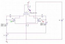
here is the schematic. R2 controls the gain (together with the xfrm). Bias runs just shy of 30ma (clearly in Class B).
Vs. Susan's follower, this requires matched pairs, but has higher gain - this particular one swings 40vpp on the 4ohm load - > 20wrms. you will need two more resistors to properly control feedback.
if that's what your degree gave you, I would go back, ask them for a complete refund of your tuition, and sue for punitive damages. You would have a pretty good case there.
just exactly what bias current did Susan specify?
Even if your engineering training couldn't help you see this, others' simulation, including Susan's own simulation, should have shown you without doubt how wrong your above statement is.
Should I go by your house tomorrow morning and pick up your engineering degree in a garbage back?
Good night.
I also dialed in a little bit feedback, as Nelson did.
Running off a pair of FQA19N20, it sounded pretty good too.
Simulation shown that you need a very strong pre-amp to drive this, as the FQAs have high gate capacitance. so I am thinking about pairing them up with a set of pre-drivers (medium powered NPNs capable of delivering 20ma at about 50v).
here is the schematic. R2 controls the gain (together with the xfrm). Bias runs just shy of 30ma (clearly in Class B).
Vs. Susan's follower, this requires matched pairs, but has higher gain - this particular one swings 40vpp on the 4ohm load - > 20wrms. you will need two more resistors to properly control feedback.
Roscoe Primrose said:Maybe you can, but at least two of us with engineering degrees see it otherwise...
if that's what your degree gave you, I would go back, ask them for a complete refund of your tuition, and sue for punitive damages. You would have a pretty good case there.
Roscoe Primrose said:with bias and supply voltage as she specifies,
just exactly what bias current did Susan specify?
Roscoe Primrose said:the MOSFETs won't turn off until you're essentially driving rail-to-rail at the outputs,
Even if your engineering training couldn't help you see this, others' simulation, including Susan's own simulation, should have shown you without doubt how wrong your above statement is.
Should I go by your house tomorrow morning and pick up your engineering degree in a garbage back?
Good night.
Attachments
tlf9999 said:just exactly what bias current did Susan specify?
If you bothered to read the thread where Susan posted the simulations, you'd know that Susan biases the MOSFETs at 750mA per MOSFET with a +34V supply.
Even if your engineering training couldn't help you see this, others' simulation, including Susan's own simulation, should have shown you without doubt how wrong your above statement is.
What a crock. Just go back and look at BOTH of the simulations Susan posted. Yes, the simulation clearly shows class AB operation with 100mA/MOSFET. However, the second simulation, with the MOSFETs biased at 375mA shows no cutoff of either MOSFET through the entire AC signal, clearly class A operation. The linearity would be further improved at 750mA/MOSFET.
Hi Susan,
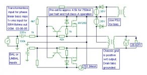
Following on from my delightfully smooth sounding results and thoughts about bass phase linearity when the signal source does not have a low driving impedance/resistance, I came up with this attached suggested circuit.
There is still no global feedback, yet the loudspeaker damping is further improved.
This circuit is again delightfully simple, and retains class-A operation with lower than 750mA per half quiescent currents. This is because the Mosfet drive voltage is related to the output transformer centre tap, and not the Mosfet sources (bipolar emitters), as is the case with 99.9% of all other amplifier circuits.
I shall be making a bipolar version shortly so that I can go for higher power with paralleled output devices.
Cheers ......... Graham.
PS. I cannot say anything at all positive about one subscriber's recent contributions, so I am saying nothing.
Hi tlf9999. You could take a look at the 220 ohm resistors related to the lower output Mosfet of your own separately posted circuit !!!
Attachments
Graham Maynard said:This circuit ... retains class-A operation with lower than 750mA per half quiescent currents.
All of my Class B amps do that, strangely.
Graham Maynard said:Hi tlf9999. You could take a look at the 220 ohm resistors related to the lower output Mosfet of your own separately posted circuit !!!
What about them? Would love to know.
Hi Susan,
Further to my suggested circuit above, which is a 'minimum device' arrangement; it is of course possible to add a 2x bipolar 8 > 10mA adjustable current source connected to the drain rail in place of the tail resistor and extra positive supply rail.
It is also worth noting that the additional input transistors not only increase input sensitivity, but they compare the voltage developed across the ouput transformer with input via a local differential and resistively self balancing shunt feedback. This additionally counters the small shift of the ac zero wrt transformer centre tap which arises due to non-linear per half output conduction. Thus the waveform at either end of the transformer can be fractionally distorted wrt to chassis or centre tap, whilst the differential voltage across both primaries, and thus the voltage developed by the secondary, is minimally distorted.
Ideally (in the absence of an input transformer) the signal source for my circuit would be low impedance plus balanced to permit equal maximum output voltage clipping. In unbalanced mode approximately one volt less output swing is available to the driven half.
Hi tlf9999,
Yes the different natural transconduction mode within Mosfets can maintain class-A operation in a circuit where bipolars would run in class-AB. I have had single and Darlington bipolars running smoothly in this transformer coupled circuit, and because of the centre tapped biasing arrangement, where the bias is not a separate entity external to the signal path, they too maintain class-A operation. An equal bias in other 'conventional' transformer push-pull arrangements allows bipolars to dissonantly fall into class-AB.
Sure, it is even possible to put Mosfets in a JLH class-A and run it in class-A with say 300mA of quiescent, where 2A is necessary with bipolars, though then the Mosfet characteristics alter dynamic operation and stability requirements. Conversely Susan's efficient transformer coupled class-A circuit is especially good with Mosfets; bipolars can still work well, but with their base current requirements are not naturally suited to high impedance input transformer drive. Here it takes extra complexity to make bipolars do what Mosfets do anyway.
(I was thinking of the voltage drop/loss the 220 ohm resistors are obliged to set up.)
Cheers ......... Graham.
Hi Graham,
Thank you for these suggestions, certainly looks interesting.
The single and simple supply is one of the things I like to keep, although the additional supplies don't need to be high current.
Will be interesting to see how this translates into practice.
With my input transformer (1:10 or 1:20 step up) the input impedance needs to be about 120 K ohms, so a couple of R values would need to be twiddled with for the base inputs?
For the 600 ohm 1:4 step up these value are close (needs 10K termination).
And one would lose those input capacitors.
Thanks again for your input.
Best wishes,
Susan.
Thank you for these suggestions, certainly looks interesting.
Graham Maynard said:Hi Susan,
Further to my suggested circuit above, which is a 'minimum device' arrangement; it is of course possible to add a 2x bipolar 8 > 10mA adjustable current source connected to the drain rail in place of the tail resistor and extra positive supply rail.
The single and simple supply is one of the things I like to keep, although the additional supplies don't need to be high current.
It is also worth noting that the additional input transistors not only increase input sensitivity, but they compare the voltage developed across the output transformer with input via a local differential and resistively self balancing shunt feedback. This additionally counters the small shift of the ac zero wrt transformer centre tap which arises due to non-linear per half output conduction. Thus the waveform at either end of the transformer can be fractionally distorted wrt to chassis or centre tap, whilst the differential voltage across both primaries, and thus the voltage developed by the secondary, is minimally distorted.
Will be interesting to see how this translates into practice.
Ideally (in the absence of an input transformer) the signal source for my circuit would be low impedance plus balanced to permit equal maximum output voltage clipping. In unbalanced mode approximately one volt less output swing is available to the driven half.
With my input transformer (1:10 or 1:20 step up) the input impedance needs to be about 120 K ohms, so a couple of R values would need to be twiddled with for the base inputs?
For the 600 ohm 1:4 step up these value are close (needs 10K termination).
And one would lose those input capacitors.
Thanks again for your input.
Best wishes,
Susan.
Graham Maynard said:Yes the different natural transconduction mode within Mosfets can maintain class-A operation in a circuit where bipolars would run in class-AB.
I failed to see how this could be an issue (aside from the fact that low beta bipolars can overload the input transformer but that issue is present with power MOSFETs that have high gate capacitance - I have simulated a variation of Susan's design, when I am not out collecting garbage, where the MOSFETS are driven by medium-power bipolars and it substantially improved performance.
Again, aside from assertions, I have not seen concrete evidence that MOSFETS have some magic here that bipolars don't.
(I was thinking of the voltage drop/loss the 220 ohm resistors are obliged to set up.)
The voltage drop off there has nothing to do with the value of the resistors. Maybe I missed something here?
tlf9999 said:I work in the sanitary industry (another way to say that I am a garbage collector) and have to work 2-3 jobs to help pay for rent and food.
Some thing tells me you are in fact Dr. (Prof) Choma???

- Home
- Amplifiers
- Solid State
- Zero Feedback Impedance Amplifiers