--> Amp Changes 2 - running
Hi Susan,
thanks a lot for your replies !
I bought only 50 IRF 530N over Ebay for about 12 EURO.
And i match any parts, so i have many IRF 530N from 4,19V - 4,22V.
I think qty of 25 my bee enough.
The TR1 with 2x 12V 30VA is only a test Transformator, i read the tread about the "bifilar windings", but i have no dealer today.
I don't know if the TR1 has "bifilar 12 volt windings", i thing about to use the "E. J. Sowter #8160".
Do you know how mutch the #8160 cost ?
Fantastic, no i understand more and more how to drive the Zeus Amp -
i am excited !
Where can I buy the OP275 or the TPA6120 in Germany or Europe ?
a nice day - to day - uwe
Hi Susan,
thanks a lot for your replies !
Susan-Parker said:Excellent.
How many parts did it take to get three matched up?
I bought only 50 IRF 530N over Ebay for about 12 EURO.
And i match any parts, so i have many IRF 530N from 4,19V - 4,22V.
I think qty of 25 my bee enough.
Are you thinking of a 2 stage version of the ampifier (the input toroid TR1 you are using should have bifilar 12 volt windings)?
The TR1 with 2x 12V 30VA is only a test Transformator, i read the tread about the "bifilar windings", but i have no dealer today.
I don't know if the TR1 has "bifilar 12 volt windings", i thing about to use the "E. J. Sowter #8160".
Do you know how mutch the #8160 cost ?
Or a line driver?
-- Post #440 --
Okay, had a look at the Behringer UB802 specs.
You could add a balanced line driver using op amps, e.g. the OP275
http://hjem.get2net.dk/tkhifi/data-blade/op275.pdf
Figure 17, page 10.
Which is the part I used originally with my input transformer set for 150 or 600 ohm impedance. Whilst not everyone's cup of tea the op275 is specified to work into a 600 ohm load and seems to cope okay with 150 ohms.
For lower input impedances (and nice square wave test results) the current drive TI TPA6120 part works better but if one is using both sides to drive one transformer it is necessary to use the center tap of the 12V-0-12V returned to the driver's 0 volts as well otherwise the TPA6120 complains (big time).
Fantastic, no i understand more and more how to drive the Zeus Amp -
i am excited !
Where can I buy the OP275 or the TPA6120 in Germany or Europe ?
a nice day - to day - uwe
it should not be any problem.There is only 0,35 ohms DC resistans on either side of the loudspeaker,and that should take most of the current until the fuse blows..Just make sure that the mosfets do have their gate protection as if one goes your speaker won't be happy.
Re: --> Amp Changes 2 - running
Hi Uwe,
And thank you for your interest and enthusiasm.
50 IRF530N for 12 Euro sounds a good buy to me - opening another browser window quickly and seeing if there are any more going.
It's difficult to know definitely unless the transformer manufacturer actually specifies it.
The 8160 "interstage" transformer, Standard model 8160 with M6 core will be approximately UKP 70 each, plus VAT as appropriate, and shipping.
Discounts:
6 off = 10%
13 off = 15%
25 off = 20%
A M6/Mumetal 50/50% core version will be about 25% more expensive.
Note however that Mumetal saturates at a lower level than M6 (40%?) so a 100% Mumetal core is not advised.
(I have some Mumetal laminations to try out but still need to set up to be able to test these - unfortunately life has kept me busy.)
N.B. I have added this pricing info to the input transformer page.
Excellent")
Digikey - http://de.digikey.com
OP275 are Euro 1.64 each.
TPA6120 are Euro 3.45 each.
If you don't feel up to doing a special on PTH micro board PCBs for the TPA6120 are available from
http://home.swipnet.se/~w-50719/hifi/qrv07/index.html
Note to All: Personally it is relatively easy for me to make up the TPA6120 driver the hard way on the micro board, but I would NOT recommend this to anyone who isn't considerably experienced in surface mount technology and has a really good temperature controlled soldering iron with very fine tips.
Hope this helps.
Best wishes,
Susan.
Hi Uwe,
dx.master said:Hi Susan,
thanks a lot for your replies !
I bought only 50 IRF 530N over Ebay for about 12 EURO.
And i match any parts, so i have many IRF 530N from 4,19V - 4,22V.
I think qty of 25 my bee enough.
And thank you for your interest and enthusiasm.
50 IRF530N for 12 Euro sounds a good buy to me - opening another browser window quickly and seeing if there are any more going.
The TR1 with 2x 12V 30VA is only a test Transformator, i read the tread about the "bifilar windings", but i have no dealer today.
I don't know if the TR1 has "bifilar 12 volt windings",
It's difficult to know definitely unless the transformer manufacturer actually specifies it.
i thing about to use the "E. J. Sowter #8160".
Do you know how mutch the #8160 cost ?
The 8160 "interstage" transformer, Standard model 8160 with M6 core will be approximately UKP 70 each, plus VAT as appropriate, and shipping.
Discounts:
6 off = 10%
13 off = 15%
25 off = 20%
A M6/Mumetal 50/50% core version will be about 25% more expensive.
Note however that Mumetal saturates at a lower level than M6 (40%?) so a 100% Mumetal core is not advised.
(I have some Mumetal laminations to try out but still need to set up to be able to test these - unfortunately life has kept me busy.)
N.B. I have added this pricing info to the input transformer page.
Fantastic, no i understand more and more how to drive the Zeus Amp -
i am excited !
Excellent
Where can I buy the OP275 or the TPA6120 in Germany or Europe ?
a nice day - to day - uwe
Digikey - http://de.digikey.com
OP275 are Euro 1.64 each.
TPA6120 are Euro 3.45 each.
If you don't feel up to doing a special on PTH micro board PCBs for the TPA6120 are available from
http://home.swipnet.se/~w-50719/hifi/qrv07/index.html
Note to All: Personally it is relatively easy for me to make up the TPA6120 driver the hard way on the micro board, but I would NOT recommend this to anyone who isn't considerably experienced in surface mount technology and has a really good temperature controlled soldering iron with very fine tips.
Hope this helps.
Best wishes,
Susan.
Re: Balanced Line Drivers
Aaaah, glad to see we have finally breeched the oh-so-important topic of how to get a balanced/differential signal to feed the Zeus amp. There a few other threads around here on the subject .
Peter Daniel started a similar thread on this subject in which Carlosfm suggested the Analog Devices AD815 as great sounding basis for differential or single-ended to differential preamps. Although, it looks like that thread is fading to an end, maybe we can move the subject forward.
The datasheet has three interesting designs for SE to Diff line drivers.
But, Wensan posted today that:
So, that brings us to the final design:
Thoughts anyone?
I'm ordering up some samples(including AD826) and hopefully the great evaluation board they have for the AD815.
Susan-Parker said:You could add a balanced line driver using op amps, e.g. the OP275
Aaaah, glad to see we have finally breeched the oh-so-important topic of how to get a balanced/differential signal to feed the Zeus amp. There a few other threads around here on the subject .
Peter Daniel started a similar thread on this subject in which Carlosfm suggested the Analog Devices AD815 as great sounding basis for differential or single-ended to differential preamps. Although, it looks like that thread is fading to an end, maybe we can move the subject forward.
The datasheet has three interesting designs for SE to Diff line drivers.
Another means for creating a differential signal from a single ended signal is to use a transformer with a center-tapped secondary. The center tap of the transformer is grounded and the two secondary windings are connected to obtain opposite polarity signals to the two inputs of the AD815 amplifiers. The bias currents for the AD815 inputs are provided by the center tap ground connection through the transformer windings.
One advantage of using a transformer is its ability to provide isolation between circuit sections and to provide good commonmode rejection. The disadvantages are that transformers have no dc response and can sometimes be large, heavy, and expensive.
This circuit is shown in Figure 51.
An externally hosted image should be here but it was not working when we last tested it.
Direct Single-Ended-to-Differential Conversion
Two types of circuits can create a differential output signal from a single-ended input without the use of any other components than resistors. The first of these is illustrated in Figure 52.
Amp 1 has its + input driven with the input signal, while the + input of Amp 2 is grounded. Thus the – input of Amp 2 is driven to virtual ground potential by its output. Therefore Amp 1 is configured for a noninverting gain of five, (1 + RF1/RG), because RG is connected to the virtual ground of Amp 2’s – input. When the + input of Amp 1 is driven with a signal, the same signal appears at the – input of Amp 1. This signal serves as an input to Amp 2 configured for a gain of –5, (–RF2/RG). Thus the two outputs move in opposite directions with the same gain and create a balanced differential signal.
This circuit can work at various gains with proper resistor selection. But in general, in order to change the gain of the circuit, at least two resistor values will have to be changed. In addition, the noise gain of the two op amps in this configuration will always be different by one, so the bandwidths will not match.
An externally hosted image should be here but it was not working when we last tested it.
But, Wensan posted today that:
The circuit of Figure 52 has phase delay problem between Vout+ and Vout-.
We can see the invert input of AMP2 as a Virtual GND,
So AMP1 is a standard noninvert amp.
The AMP2 is a standard invert amp,the Virtual Vin is its input.
The Virtual Vin a divided voltage from Vout+.
So Virtual Vin and Vout+ have the same phase delay.
But there has phase delay between Virtual Vin and Vout-.
So there has phase delay between Vout+ and Vout-.
So, that brings us to the final design:
A second circuit that has none of the disadvantages mentioned in the above circuit creates a differential output voltage feedback op amp out of the pair of current feedback op amps in the AD815. This circuit, drawn in Figure 53, can be used as a high power differential line driver, such as required for ADSL (asymmetrical digital subscriber loop) line driving.
Each of the AD815’s op amps is configured as a unity gain follower by the feedback resistors (RA). Each op amp output also drives the other as a unity gain inverter via the two RBs, creating a totally symmetrical circuit.
An externally hosted image should be here but it was not working when we last tested it.
If the + input to Amp 2 is grounded and a small positive signal is applied to the + input of Amp 1, the output of Amp 1 will be driven to saturation in the positive direction and the output of Amp 2 driven to saturation in the negative direction. This is similar to the way a conventional op amp behaves without any feedback.
If a resistor (RF) is connected from the output of Amp 2 to the + input of Amp 1, negative feedback is provided which closes the loop. An input resistor (RI) will make the circuit look like a conventional inverting op amp configuration with differential outputs. The inverting input to this dual output op amp becomes Pin 4, the positive input of Amp 1.
The gain of this circuit from input to either output will be ± RF/RI. Or the single-ended-to-differential gain will be 2 X RF/RI.
The differential outputs can be applied to the primary of a transformer. If each output can swing ±10 V, the effective swing on the transformer primary is 40 V p-p. The optional capacitor can be added to prevent any dc current in the transformer due to dc offsets at the output of the AD815.
Thoughts anyone?
I'm ordering up some samples(including AD826) and hopefully the great evaluation board they have for the AD815.
You can create an extremely accurate and low distortion diff output from an SE input using a split load emitter follower with a floating power supply.
A conventional emitter follower is set up using an NPN BJT with a supply to the collector, emitter resistor which is split into two equal, series parts, and the negative supply to the bottom of these two resistors. The center of the two series emitter resistors is grounded. The base is biased from a divider string between the positive and negative supply, but the supply is fully floating, which means the winding/frame capacitance should be low.
Output signal is taken capacitively from the emitter and from the negative supply rail. These are exactly and precisely balanced, and both of very low impedance. The circuit, pioneered by a Frenchman whose name escapes me, is eminently suited to tubes as well. The one difficulty is the fully floating supply, but with SS this is not terribly difficult.
Don't ask me how it sounds. I haven't a clue but the idea is extremely elegant and simple.
Cheers,
Hugh
Hi bobo1on1,
Hum, not sure why this would happen.
How are you driving the inputs (your schematic shows one input as IN-GND although I assume this is not actually the case)?
What is the lowest frequency you are driving at full power?
What is the real power supply voltage?
Looking at the irf540 data sheet you should be good for more than 30 amps per device but perhaps this is being exceeded?
0.35 ohms and 30 volts is 86 amps at DC.
I would have thought the fuse after the storage capacitors would have shriveled long before this.
Um.
More info....
Best wishes,
Susan.
bobo1on1 said:After blowing another pair of irf540's, I came to the conclusion the fets need another pair of zeners for protection so the max Vdss won't be exceeded.
D1 and D2 in the schematic.
Hum, not sure why this would happen.
How are you driving the inputs (your schematic shows one input as IN-GND although I assume this is not actually the case)?
What is the lowest frequency you are driving at full power?
What is the real power supply voltage?
Looking at the irf540 data sheet you should be good for more than 30 amps per device but perhaps this is being exceeded?
0.35 ohms and 30 volts is 86 amps at DC.
I would have thought the fuse after the storage capacitors would have shriveled long before this.
Um.
More info....
Best wishes,
Susan.
Susan-Parker said:Hi bobo1on1,
Hum, not sure why this would happen.
How are you driving the inputs (your schematic shows one input as IN-GND although I assume this is not actually the case)?
What is the lowest frequency you are driving at full power?
What is the real power supply voltage?
Looking at the irf540 data sheet you should be good for more than 30 amps per device but perhaps this is being exceeded?
0.35 ohms and 30 volts is 86 amps at DC.
I would have thought the fuse after the storage capacitors would have shriveled long before this.
Um.
More info....
Best wishes,
Susan.
Hi Susan and bobo1on1,
Ur Mosfets are damaging because their gate to Source voltage is
exceeds the VGS limit.
Ur implementation of zeners is totally wrong. instead u must use 11V back to back Zeners and their is no need of 80V zeners. Simply lower the rail voltage or use IRF640N 200V mosfet .
The Transformer is creating a sort of TRICKLE FLYBACK although Body diodes are present but they also avalanche due to this effect and the mosfets are damaged.
Hope this Helps
Schematic Update
Hi,

Update schematic showing zener protection as per IR recommendations.
I have mentioned this in previous posts but I should have updated this schematic. The previous version was as drawn in 1994.
I apologize for this as I have come to realize that once the posts move on to the next page it become quickly quite difficult to remember where things are.
I spent a while yesterday trying to find the post with the Sowter input transformer price info as I couldn't find the email - then realized that I had had this from my phone conversation - oops!
The image (once one has refreshed the browser cache) should now appear correctly in the
http://www.susan-parker.co.uk/zeus.htm
and other pages as well.
However I have run configurations like the previous schematic with the zener across the mosfet directly and whilst I have managed to get the mosfet to take off there are only little squibs of RF on part of the cycle and the mosfets themselves haven't minded.
Of course with the output transformer capable of radiating up into the many megahertz region this is not a good idea from the EMC/RFI point of view.
Because the mosfet is a follower it has a voltage gain just under unity - so parasitic oscillation doesn't amplify unlike mosfets used as voltage gain.
However I am sure that there are still lots of possibilities to let the magic smoke out. Partly why I have been big on cheepie mosfets like the IRFP140s which whilst not quite throw away items like fuses don't cause massive financial grief unlike nice lateral or RF mosfets
I do applaud bobo1on1's efforts and hope we can get this sorted out before discouragement sets in.
I am meant to be working at the moment, hence lack of replies on other less pressing posts.
Best wishes,
Susan.
Hi,
Update schematic showing zener protection as per IR recommendations.
I have mentioned this in previous posts but I should have updated this schematic. The previous version was as drawn in 1994.
I apologize for this as I have come to realize that once the posts move on to the next page it become quickly quite difficult to remember where things are.
I spent a while yesterday trying to find the post with the Sowter input transformer price info as I couldn't find the email - then realized that I had had this from my phone conversation - oops!
The image (once one has refreshed the browser cache) should now appear correctly in the
http://www.susan-parker.co.uk/zeus.htm
and other pages as well.
However I have run configurations like the previous schematic with the zener across the mosfet directly and whilst I have managed to get the mosfet to take off there are only little squibs of RF on part of the cycle and the mosfets themselves haven't minded.
Of course with the output transformer capable of radiating up into the many megahertz region this is not a good idea from the EMC/RFI point of view.
Because the mosfet is a follower it has a voltage gain just under unity - so parasitic oscillation doesn't amplify unlike mosfets used as voltage gain.
However I am sure that there are still lots of possibilities to let the magic smoke out. Partly why I have been big on cheepie mosfets like the IRFP140s which whilst not quite throw away items like fuses don't cause massive financial grief unlike nice lateral or RF mosfets
I do applaud bobo1on1's efforts and hope we can get this sorted out before discouragement sets in.
I am meant to be working at the moment, hence lack of replies on other less pressing posts.
Best wishes,
Susan.
Well they seem to blow up when I disconnect the speaker while it's playing at some serious power, I know I shouldn't do this, but it can happen sometime.
I think it creates a big spike on the transformer just high enough to blow up the mosfet, I am using some 800 volt mosfets right now and there is no problem at all.
So I will put in the zeners, maybe it won't do any good, but the cost is next to nothing.
Oh and I forgot to put in the fuse, again!
Right now I am using a 2x 6 v 120 VA toroid with a 16v 55000 µF cap.
The in_gnd is not the same as the psu gnd, it is the gnd coming from the signal source (my soundcard).
I can get 48 75345P power mosfets for 4 euro, I might use those, although the gate capacitance is a bit high, 4 nF.
Ehm what are back to back zeners? I did put in a 12 volt zener between the gate and the source, that should make sure the Vgs does not exceed 12 volts, or am I wrong?
I think it creates a big spike on the transformer just high enough to blow up the mosfet, I am using some 800 volt mosfets right now and there is no problem at all.
So I will put in the zeners, maybe it won't do any good, but the cost is next to nothing.
Oh and I forgot to put in the fuse, again!
Right now I am using a 2x 6 v 120 VA toroid with a 16v 55000 µF cap.
The in_gnd is not the same as the psu gnd, it is the gnd coming from the signal source (my soundcard).
I can get 48 75345P power mosfets for 4 euro, I might use those, although the gate capacitance is a bit high, 4 nF.
amp_man_1 said:
Hi Susan and bobo1on1,
Ur Mosfets are damaging because their gate to Source voltage is
exceeds the VGS limit.
Ur implementation of zeners is totally wrong. instead u must use 11V back to back Zeners and their is no need of 80V zeners. Simply lower the rail voltage or use IRF640N 200V mosfet .
Ehm what are back to back zeners? I did put in a 12 volt zener between the gate and the source, that should make sure the Vgs does not exceed 12 volts, or am I wrong?
bobo1on1 said:Well they seem to blow up when I disconnect the speaker while it's playing at some serious power, I know I shouldn't do this, but it can happen sometime.
Yes it does. One of the perils of development.
BTW what is your definition of serious power?
More than 35 watts I assume
The in_gnd is not the same as the psu gnd, it is the gnd coming from the signal source (my soundcard).
Hum, you should be driving a diferential signal into the mosfets - see darkmoebius's very helpful post:
http://www.diyaudio.com/forums/showthread.php?postid=508517#post508517
However an input transformer drive will allow you to drive the gates over the nominal supply rail which could give you a few more watts.
I can get 48 75345P power mosfets for 4 euro, I might use those, although the gate capacitance is a bit high, 4 nF.
You need to look at the capacitance from the gate to the drain, not the source.
http://www.fairchildsemi.com/ds/HU/HUFA75345S3S.pdf
Figure 12 - Crss.
However if you are runing off automotive supply i.e. 14 volts then you are still up in the 1000 pF region.
Best wishes,
Susan.
bobo1on1 said:Well they seem to blow up when I disconnect the speaker while it's playing at some serious power, I know I shouldn't do this, but it can happen sometime.
I think it creates a big spike on the transformer just high enough to blow up the mosfet, I am using some 800 volt mosfets right now and there is no problem at all.
You might like to try varistors across them.
Hi mikelm,
The zeners are now connected to the other side of the gate resistor. A subtle but recomended practise by International Rectifier.
Best wishes,
Susan.
mikelm said:Hi Susan,
am I missing something ?
your posted 'new schematic' looks identical to the one that I downloaded about a week ago
The zeners are now connected to the other side of the gate resistor. A subtle but recomended practise by International Rectifier.
Best wishes,
Susan.
A big inductanse will keep on raising the voltage until the energy from the collapsing magnetic field is wasted somehow. Usually you have a spark through the isolation of the windings. I got a jolt from a big transformer that was several thousands of volts once....Well they seem to blow up when I disconnect the speaker while it's playing at some serious power, I know I shouldn't do this, but it can happen sometime.
I got rid of the problem with fets blowing up when i connected 18 volts 1,3 watts zeners back to back between gate and source..
My amp is very happily putting out 115 watts of clean dynamic power into 4-8 ohms, without a trace of fatigue or distorsion.
-AND THE SOUND IS WONDERFUL!!!!!!!!!!!!!!!!!!!!!!!!!!!!!!!
For all of you that have read Allen Wright`s Tube preamp......: "DDR" is outstanding!!!!!
Spead and dynamics is WONDERFULL!!!
I love this amp!!!!
Thank you Susan!!!!!!!!!!!
Hi Circlomanen ,
Have you any information about the Tr1 an Tr2 ?
And any pictures ?
Which Mosfet do you use and what about the Biascontrol ?
How mutch current go through the Mosfets ?
I use now 0,65A through every Mosfet, that sounds good.
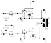
Look at the Schematic:
Changes: Rx = 7,5Ohm.
- uwe
Circlomanen said:My amp is very happily putting out 115 watts of clean dynamic power into 4-8 ohms, without a trace of fatigue or distorsion.
-AND THE SOUND IS WONDERFUL!!!!!!!!!!!!!!!!!!!!!!!!!!!!!!!
For all of you that have read Allen Wright`s Tube preamp......: "DDR" is outstanding!!!!!
Spead and dynamics is WONDERFULL!!!
I love this amp!!!!
Have you any information about the Tr1 an Tr2 ?
And any pictures ?
Which Mosfet do you use and what about the Biascontrol ?
How mutch current go through the Mosfets ?
I use now 0,65A through every Mosfet, that sounds good.
Look at the Schematic:
An externally hosted image should be here but it was not working when we last tested it.
. 
Changes: Rx = 7,5Ohm.
- uwe
Tr 1 is a standard 50 VA toroid vith a singel 24 volt secondary and a split 115+115 volt primary coupled backwards.Have you any information about the Tr1 an Tr2 ?
Tr2 is a centertapped Choke winded on a E150 laminationstack with normal plastic isolated 1mm2 coupling wire, 71 turns trifilar at the moment,i will rewind it as soon as i get any time to do it.
The mosfets are IRFP250/IR with 300 ohm gatestoppers.
Bias is 355 mA / Fet.
Bias-controll is a 7,5 volt Zener as a voltage-referece, a 100 K pot and a P-chanel IRF9620 as a buffer/thermal feedback- to give the transformer midpoint a low impedans and a stabel V-ref. Cold it runns 320 mA of current/Fet, after 2 hours and a temp-rise of 15 degrees celcius it runns 355 mA, and seems as it has stabilised.
No Im sorry, It looks like a birdnest in the midle of a tornado, its just a prototyp to check out the sound and how it works.And any pictures ?
Susan-Parker said:
Yes it does. One of the perils of development.
BTW what is your definition of serious power?
More than 35 watts I assume
Hum, you should be driving a diferential signal into the mosfets - see darkmoebius's very helpful post:
http://www.diyaudio.com/forums/showthread.php?postid=508517#post508517
However an input transformer drive will allow you to drive the gates over the nominal supply rail which could give you a few more watts.
Best wishes,
Susan.
It was running at about 40 watts into a 4 ohm speaker, which is alot for an old philips speaker from 1974.
The output from my soundcard is a differential signal, it just depends on how you look at it, remember the psu from the amplifier is completely seperated from the computer's psu, the only electrical connection between them is the sound connection.
So in that way the soundcard puts a voltage over the 1k resistors, which has the same effect as using a transformer, the only difference beeing the galvanic separation.
Oh and if I am going to use those cheap fets with high capacitance I will probably drive them with an opamp like transistor circuit which can deliver a reasonable amount of current to drive the gates, maybe something in class A with 500 mA idle current or something.
- Home
- Amplifiers
- Solid State
- Zero Feedback Impedance Amplifiers