Hi bobo1on1,
Okay.
Pity. For bifilar windings you could thread the wire - similar to winding a torroid. A pain but for 150 turns doable with patience.
You should be able to get about seven volts peak to peak for 10 dBm at 600 ohms.
So two will give you 14 volts across the transformer, about eight to ten watts (max) into eight ohms.
Bandwidth a bit limited.
But always good for a test bench trial, the bits for this amp are very quick to try out as there are only a few wires to change around.
All the best.
Best wishes,
Susan.
bobo1on1 said:
Susan: I connected two more audio transformers, the primary windings in parallel and the secondary windings in series to double the voltage, the amp still distorts at low frequencies but at a slightly higher volume level.
I found out that the distortion sort of shifts up to a higher level when I increase the bias voltage, so there is a good chance the audio transformers are getting saturated.
Okay.
I am going to rewind the output transformer, but someone thought it was a good idea to weld the laminations together so I can't get them apart.
Pity. For bifilar windings you could thread the wire - similar to winding a torroid. A pain but for 150 turns doable with patience.
Do you think think two of these audio transformers wil do the job? the specs are: 15Kohm-60Kohm,200c-1kc size:23-36 mm,audio level:+10dbM.
Does anyone know what kind of value c is?
I've also included a picture.
You should be able to get about seven volts peak to peak for 10 dBm at 600 ohms.
So two will give you 14 volts across the transformer, about eight to ten watts (max) into eight ohms.
Bandwidth a bit limited.
But always good for a test bench trial, the bits for this amp are very quick to try out as there are only a few wires to change around.
All the best.
Best wishes,
Susan.
I just managed to open the transformer, I used a saw to cut trough the welds and used a screwdriver to crack it open, now I can start rewinding it.
When winding 150 turns bifilar do you mean 75 turns for each wire and the two wires fitted exactly parallel?
Oh btw don't set the bias too high without wearing protective glasses
When winding 150 turns bifilar do you mean 75 turns for each wire and the two wires fitted exactly parallel?
Oh btw don't set the bias too high without wearing protective glasses
Hi bobo1on1,
Victory!
150 turns each wire, both wires wound simultaneously and sitting next to each other.
This produces an interleave effect.
1:2;1:2,1:2;1:2,1:2;1:2 ..... 1:2
and then when you get to the end you wind back across and because the wire is then spiraling the other way you get cross linking of the 1 and 2 wires between the layers as well.
1:2;1:2;1:2;1:2;1:2;1:2 ..... 1:2-
-1:2;1:2;1:2;1:2;1:2;1:2 ..... 1:2
1:2;1:2;1:2;1:2;1:2;1:2 ..... 1:2-
-1:2;1:2;1:2;1:2;1:2;1:2 ..... 1:2
1:2;1:2;1:2;1:2;1:2;1:2 ..... 1:2-
etc.
Key:
1 and 2 = wire
: = wire pair wound together
; = pairs of wires
- = small offset for part of turn at end.
..... = further pairs of wires to fill layer
You should have approximately 150 turns - but a few more or less won't matter greatly.
I buy the enameled wire in sets of four bobbins - although you will only need two for this version - so I don't have to mess around with re-spooling.
When winding the bobbin the above should become clear.
Which is why I use a 5 volt regulator and recommend a multi-turn pot, the adjustment for the bias is quite sensitive.
I have found that I need to set the bias somewhere around the three and a half volts point, but this can vary quite considerably (by several hundred millivolts) depending on mosfet type and manufacturer.
And a fast 6 amp fuse AFTER the power supply smoothing cap. Fuses are cheaper than mosfets.
... you can no doubt imagine how I worked that one out! Bang!
(I also have a 0.1 ohm power resistor in the supply line to measure the current (if you look at the picture of my amp on the web page you can just see it (gold smudge) snuggling under the terminals of the smoothing capacitor). There is also a 47K wire wound across the cap to discharge it once the power is turned off.)
Excellent.
Best wishes,
Susan.
bobo1on1 said:I just managed to open the transformer, I used a saw to cut trough the welds and used a screwdriver to crack it open, now I can start rewinding it.
When winding 150 turns bifilar do you mean 75 turns for each wire and the two wires fitted exactly parallel?
Victory!
150 turns each wire, both wires wound simultaneously and sitting next to each other.
This produces an interleave effect.
1:2;1:2,1:2;1:2,1:2;1:2 ..... 1:2
and then when you get to the end you wind back across and because the wire is then spiraling the other way you get cross linking of the 1 and 2 wires between the layers as well.
1:2;1:2;1:2;1:2;1:2;1:2 ..... 1:2-
-1:2;1:2;1:2;1:2;1:2;1:2 ..... 1:2
1:2;1:2;1:2;1:2;1:2;1:2 ..... 1:2-
-1:2;1:2;1:2;1:2;1:2;1:2 ..... 1:2
1:2;1:2;1:2;1:2;1:2;1:2 ..... 1:2-
etc.
Key:
1 and 2 = wire
: = wire pair wound together
; = pairs of wires
- = small offset for part of turn at end.
..... = further pairs of wires to fill layer
You should have approximately 150 turns - but a few more or less won't matter greatly.
I buy the enameled wire in sets of four bobbins - although you will only need two for this version - so I don't have to mess around with re-spooling.
When winding the bobbin the above should become clear.
Oh btw don't set the bias too high without wearing protective glasses
Which is why I use a 5 volt regulator and recommend a multi-turn pot, the adjustment for the bias is quite sensitive.
I have found that I need to set the bias somewhere around the three and a half volts point, but this can vary quite considerably (by several hundred millivolts) depending on mosfet type and manufacturer.
And a fast 6 amp fuse AFTER the power supply smoothing cap. Fuses are cheaper than mosfets.
... you can no doubt imagine how I worked that one out! Bang!
(I also have a 0.1 ohm power resistor in the supply line to measure the current (if you look at the picture of my amp on the web page you can just see it (gold smudge) snuggling under the terminals of the smoothing capacitor). There is also a 47K wire wound across the cap to discharge it once the power is turned off.)
Excellent.
Best wishes,
Susan.
Dear Bear,
You previously wrote:
I am now the proud owner of a copy of the Wireless World reprint of the Radiotron Designer's Handbook - 1st UK edition - no expense spared.
It has just arrived and whilst filled with very many interesting things I cannot find the reference to multi-filar wound output transformers.
In my eagerness and enthusiasm, and no doubt distract by all the triode valve schematics, I assume I have just missed this.
I would be most grateful if you could give me a page reference.
Many thanks.
Best wishes,
Susan.
You previously wrote:
bear said:Ok,
From memory...
Ok, as far as output transformers start with your library and back issues of Wireless World. That should be easy enough.
Then the venerable Radiotron Designer's Handbook covers a number of them with citations to the original source.
_-_-bear
I am now the proud owner of a copy of the Wireless World reprint of the Radiotron Designer's Handbook - 1st UK edition - no expense spared.
It has just arrived and whilst filled with very many interesting things I cannot find the reference to multi-filar wound output transformers.
In my eagerness and enthusiasm, and no doubt distract by all the triode valve schematics, I assume I have just missed this.
I would be most grateful if you could give me a page reference.
Many thanks.
Best wishes,
Susan.
Hi Jonathan,
It's the difference between a dull and rainy day, and a bright and sunny one.
Normal speakers and amps produce a stereo image which to me is ill defined and "somewhere between the speakers, maybe", and often has a even fuzzier hole in the middle.
For a long time I though this was normal and was puzzled by some peoples enthusiasm for imagery which didn't make any sense to me.
Then one day I heard a pair of Tannoy coaxial speakers, and it was a revelation. Suddenly there was a stage and I could place with some certainty the various sounds.
I then found a similar improvement with electrostatics.
Unfortunately I couldn't have electrostatics so I went off and did a bit of research and designed my spheres. Then the bass, then the amps and so on down the slippery slope.
I now can not only hear the precise location of every sound, but on a good recording tell if any of the musicians are moving whilst playing, the placement of a note on a xylophone, etc.
In my imagination I can hear the rosin falling off the bow as a soloist plays her Strad. This is probably somewhat optimistic, but reflects the enthusiasm I can feel to a well recorded and produced piece of music, even with the limitations of CDs.
I hope this goes some way to answering your question.
Best wishes,
Susan.
Jonathan Bright said:Susan, greeting from Oz again. Not exactly on the topic of amps, but a couple of times in this thread you have mentioned your sensitivity to phase distortion. Is it possible, please, for you to describe the reaction you have? (If the previous objective material has created chaos I hope a subjective comment won't be a complete nightmare.) Thanks Jonathan.
It's the difference between a dull and rainy day, and a bright and sunny one.
Normal speakers and amps produce a stereo image which to me is ill defined and "somewhere between the speakers, maybe", and often has a even fuzzier hole in the middle.
For a long time I though this was normal and was puzzled by some peoples enthusiasm for imagery which didn't make any sense to me.
Then one day I heard a pair of Tannoy coaxial speakers, and it was a revelation. Suddenly there was a stage and I could place with some certainty the various sounds.
I then found a similar improvement with electrostatics.
Unfortunately I couldn't have electrostatics so I went off and did a bit of research and designed my spheres. Then the bass, then the amps and so on down the slippery slope.
I now can not only hear the precise location of every sound, but on a good recording tell if any of the musicians are moving whilst playing, the placement of a note on a xylophone, etc.
In my imagination I can hear the rosin falling off the bow as a soloist plays her Strad. This is probably somewhat optimistic, but reflects the enthusiasm I can feel to a well recorded and produced piece of music, even with the limitations of CDs.
I hope this goes some way to answering your question.
Best wishes,
Susan.
With my amp, which have not only nine devices and miracle trannys, I can listen moving of musicians, space behind and silence between notes, but only with on some recording and with some boxes. " Hole " between boxes is mainly caused by wrong position of boxes and it is any miracle, if you havn't it.
With my amp, which have not only nine devices and miracle trannys, I can listen moving of musicians, space behind and silence between notes, but only with on some recording and with some boxes. " Hole " between boxes is mainly caused by wrong position of boxes and it is any miracle, if you havn't it.
I hope there will be a day you will become tired to tell us. For you its ok to listen whatever you want on a 900 devices amp, for others its ok to listen to lightbulbs and transformers. You have to accept this.
I think imaging is related to room acoustics and speaker matching, not to amplifiers. Amplifiers show almost perfect gain and phase matching between channels [sometimes too small to measure] while speakers show small differences between units [usually in the crossover regions] and rooms show absolutely huge errors between channels in sound propagation
In my experience, everything produces clear imaging outdoors but anything produces difuse imaging in 3m x 4m rooms [provided a recording with some spatial information]
Room reflected sound allways trashes imaging [it masks the original reflections and phase differences from the recording], and direct radiating speakers featuring wide directivity placed in untreated rooms cause more chaotic reflected energy than direct energy to reach the listening point [very difuse imaging]
But I also blamed amplifiers until I learnt about speakers and room acoustics
I'm thinking about using toroids as output transformers because normal power transformers seem to work fine when only using the secondary windings, and they are sort of bifilar wound.
The ones I can get for a very low price (€8,50) are 80 VA 2x35 volt or 80 VA 2x 24 volt, which one would be better?
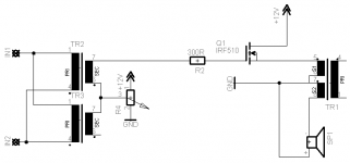
Since one fet blew up I've rebuilt it temporarily to work with just one fet, it's sort of class A now and still works fine, I've included a schematic.
The ones I can get for a very low price (€8,50) are 80 VA 2x35 volt or 80 VA 2x 24 volt, which one would be better?
Since one fet blew up I've rebuilt it temporarily to work with just one fet, it's sort of class A now and still works fine, I've included a schematic.
Attachments
Calling darkmoebius and all interested builders,
Ed Richardson at http://www.thomas-skinner.com/single_phase.htm
returned my call today. Introduced him to the forum and this thread.
Ed will contact Susan for specifications and then post that information here on this thread for all to access. Take note that he sells laminations, not transformers. Roll yur own. He said they might make a link on their page for us to order exactly what is needed. Don't want to put words in his mouth.
Prosit
Susan-Parker said:Hi bobo1on1,
Victory!
150 turns each wire, both wires wound simultaneously and sitting next to each other.
This produces an interleave effect.
1:2;1:2,1:2;1:2,1:2;1:2 ..... 1:2
and then when you get to the end you wind back across and because the wire is then spiraling the other way you get cross linking of the 1 and 2 wires between the layers as well.
1:2;1:2;1:2;1:2;1:2;1:2 ..... 1:2-
-1:2;1:2;1:2;1:2;1:2;1:2 ..... 1:2
1:2;1:2;1:2;1:2;1:2;1:2 ..... 1:2-
-1:2;1:2;1:2;1:2;1:2;1:2 ..... 1:2
1:2;1:2;1:2;1:2;1:2;1:2 ..... 1:2-
etc.
Key:
1 and 2 = wire
: = wire pair wound together
; = pairs of wires
- = small offset for part of turn at end.
..... = further pairs of wires to fill layer
You should have approximately 150 turns - but a few more or less won't matter greatly.
<snip>
Susan,
I can't quite make out the code in your cipher!
I thought you said you had a bifilar winding for the primary... which would be two wires wound side by side...
But, if you had two primary windings side-by-side and added a secondary winding to that, you'd have a Trifilar wound situation!

Susan-Parker said:Dear Bear,
You previously wrote:
I am now the proud owner of a copy of the Wireless World reprint of the Radiotron Designer's Handbook - 1st UK edition - no expense spared.
It has just arrived and whilst filled with very many interesting things I cannot find the reference to multi-filar wound output transformers.
In my eagerness and enthusiasm, and no doubt distract by all the triode valve schematics, I assume I have just missed this.
I would be most grateful if you could give me a page reference.
Many thanks.
Best wishes,
Susan.
Well the nice thing about the Radiotron Designer's Handbook is that it is a magic book. You will find that it is perfectly logical in its chapter arrangement, but that will not help you much!

The reason that is true is that as you read you will find little bitty sections of other areas that are *exactly* the thing you were looking for, but when you go back to find it again it will have slipped magically off the page into a different dimension!!
 This is true! Ask anyone who has plundered the pages of this book!
But start with the McIntosh amplifier design, and there are also pages on the various output configurations, with more references in the back as well as in the footnotes for the chapter...
All in all it is a fairly remarkable work...
I was just thinking about it...
do you mean:
A and B = wires
: = side by side wound wire
| = indicator for division between adjacent pairs (no space)
- = small offset for turn at end
... = winding to fill end of turn
where:
A:B|A:B|A:B|.... etc??
Perhaps the "1" and "2" designation is part of the ciphering issue when reading it?
_-_-bear
I used multifilar winding over 20 years ago to reduce the leakage inductance of a transformer for a 50W flyback switching power supply, and it worked pretty well. In my case, I twisted several parallel strands together, used the resulting cable to wind a transformer on a powdered iron toroid, picked the strands apart, and did series and parallel combinations to get the actual turns ratios that I needed. This is an absolute no-no for any mains isolation transformer, as the safety agencies consider magnet wire to be almost equivalent to bare wire as far as safety is concerned. However, for low voltage applications that aren't shipped to the public at large, the technique works pretty well. Double coated magnet wire will actuallly stand off 500-750VDC with no problem if not damaged. A sojurn in a tank of varnish (polyurethane varnish works ok if transformer varnish is unavailable) helps to seal up any little pinholes and inadvertant scratches, helps keep the windings from making noise, and also keeps out moisture. The transformer I wound using these techniques had << 1% leakage, low enough to allow using a modest RCD primary snubber with a 2W bleed resistor for a 50W flyback converter with 10V input. This was no mean feat, especially by early 80's standards. The losses from the powderd iron toroid (even the so-called low loss mix) were not up to the job, but that was another matter altogether....
The technique that Susan mentions of simultaneous winding using several spools of wire is another method for applying multifilar windings. If you don't want to calculate out the wire length sinvolved and hank several long, long strands together, it is the only way you can make sure of winding the transformer in one piece without any splices. If one is a real neatnik, it is possible to apply the strands side by side and wind the transformer bobbin neatly. This actually may not give quite as optimal leakage results as a sort of scramble wound technique, but will give you the best fill factor and a relatively short mean length per turn, which will reduce copper losses.
Any technique that gets the primary and secondary windings intimately intermixed will give you lower leakage than having them on seperate layers, though multiple interleaving actually works fairly well from a leakage standpoint. The MIT Radiation Lab Reference on pulse generators( authors Glasoe and Lebacqz) goes into a long discussion of optimum primary and secondary interleaving techniques for reducing both leakage inductance and stray capacitance for radar-type pulse transformers. This of course is of paramount importance for a transformer that must deliver a flat-topped high voltage pulse with little or no ringing, but canalso be applied to audio.
I don't recall any publication that talks about multifilar winding techniques except for winding the two primary halves of a push-pull transformer as a bifilar winding. Again, it is an absolute no-no for applications involvoing high voltage or safety isolation, but an obvious thing to do for low voltage applications. The reasonably low ringing shown by Susan's transformer shows that the stray capacitance introduced by this technique need not be a big concern. I plan to use multifilar windings on a large strip steel toroid when I construct my version of this amplifier. I will hank several strands together and wind as neatly as possible, not paying too much attention to which strands become primary or secondary. I expect excellent results. It should be possible to get around 0.1% leakage with such an arrangement. ~1% leakage is considered excellent for most applications.
Hi Bear,
Yes, this is correct.
I quad filar wind my transformers as I use secondary windings, but bobo1on1 is using primaries only and putting the speaker across these (in push-pull it works better with a higher impedance speaker BTW - 12 to 16 ohms, as distortion begins to rise below 8 ohms). (The single ended version has the speaker on the second winding which is now a secondary.)
So for my quad filar windings I get
A:B:C|A:B:C|A:B:C|.... etc
I keep the order across the layer but allow this to change, if it happens to be neater for the windings, to come back across.
As the wires are quite large it is important to keep the layers flat, otherwise one compromises the fill.
One can also varnish as one goes, which is effective if a bit sticky.
Best wishes,
Susan.
P.S. I am replying separately to Ed Richardson to sort out lamination styles as I understand he has received several inquiries
bear said:I was just thinking about it...
do you mean:
A and B = wires
: = side by side wound wire
| = indicator for division between adjacent pairs (no space)
- = small offset for turn at end
... = winding to fill end of turn
where:
A:B|A:B|A:B|.... etc??
Perhaps the "1" and "2" designation is part of the ciphering issue when reading it?
_-_-bear
Yes, this is correct.
I quad filar wind my transformers as I use secondary windings, but bobo1on1 is using primaries only and putting the speaker across these (in push-pull it works better with a higher impedance speaker BTW - 12 to 16 ohms, as distortion begins to rise below 8 ohms). (The single ended version has the speaker on the second winding which is now a secondary.)
So for my quad filar windings I get
A:B:C
|A:B:C|A:B:C|.... etcI keep the order across the layer but allow this to change, if it happens to be neater for the windings, to come back across.
As the wires are quite large it is important to keep the layers flat, otherwise one compromises the fill.
One can also varnish as one goes, which is effective if a bit sticky.
Best wishes,
Susan.
P.S. I am replying separately to Ed Richardson to sort out lamination styles as I understand he has received several inquiries
Hi,
For those who might be interested another square wave pic.
I am awaiting the mumetal laminations for the input transformer plus the non inductive resistors before dealing with the overshoot pulse.

... and I will be upgrading some of the line driver components.
Best wishes,
Susan.
For those who might be interested another square wave pic.
I am awaiting the mumetal laminations for the input transformer plus the non inductive resistors before dealing with the overshoot pulse.
... and I will be upgrading some of the line driver components.
Best wishes,
Susan.
Oops, clicked on the wrong button...
... so perhaps a bit more info need here.
Top trace is 1 kHz 40 volts peak to peak into 8 ohms = 50 watts.
I have added this to the test page.
http://www.susan-parker.co.uk/zeus-test-square-1khz.htm
BW,
Susan.
Susan-Parker said:Hi,
For those who might be interested another square wave pic.
... so perhaps a bit more info need here.
Top trace is 1 kHz 40 volts peak to peak into 8 ohms = 50 watts.
I have added this to the test page.
http://www.susan-parker.co.uk/zeus-test-square-1khz.htm
BW,
Susan.
- Home
- Amplifiers
- Solid State
- Zero Feedback Impedance Amplifiers