The problem with the next size up in power handling is that a suitable primary impedance is not available.  An 8 Kohm end to end impedance is "ideal". With your bookshelf speakers, you'll never know the LF roll off is present.
 ")
Practical considerations, including budget realities, are always part of my cogitations.
An 8 Kohm end to end impedance is "ideal". With your bookshelf speakers, you'll never know the LF roll off is present. Practical considerations, including budget realities, are always part of my cogitations.
hi Zach, i would recommend that even though you plan to completely rebuild it, you should still build the 12ax7 driver tube circuit from the console schematic. it would be a good way to get your "feet wet" with what is involved in the whole rebuild process. It will be like learning to ride a bike with training wheels. Since you will be waiting for the new OPTs anyway. All that will be required is 1 9 pin tube socket, some wiring, and the caps and resistors from the 12ax7 circuit. You should be able to assemble the extra circuit in a few hours if you are solder savvy.
Last edited:
Change the first tube to 12AX7, change plate resistors to 100K, adjust the feedback for the gain you want. 10-12W OUGHT to be enough for 88 dB speakers if you don't need to play really loud. Which output tap are you using?
What's the P/N on the output transformers? I've measured some similar ones, not impressive at either end of the frequency range. Better ones will extend bass and treble, won't give more power.
What's the P/N on the output transformers? I've measured some similar ones, not impressive at either end of the frequency range. Better ones will extend bass and treble, won't give more power.
hi Zach, i would recommend that even though you plan to completely rebuild it, you should still build the 12ax7 driver tube circuit from the console schematic. it would be a good way to get your "feet wet" with what is involved in the whole rebuild process. It will be like learning to ride a bike with training wheels. Since you will be waiting for the new OPTs anyway. All that will be required is 1 9 pin tube socket, some wiring, and the caps and resistors from the 12ax7 circuit. You should be able to assemble the extra circuit in a few hours if you are solder savvy.
Unfortunetely, I don't have the preamp. I could add in the 12ax7 tube, but would removing the tone circuit be tough?
Change the first tube to 12AX7, change plate resistors to 100K, adjust the feedback for the gain you want. 10-12W OUGHT to be enough for 88 dB speakers if you don't need to play really loud. Which output tap are you using?
What's the P/N on the output transformers? I've measured some similar ones, not impressive at either end of the frequency range. Better ones will extend bass and treble, won't give more power.
Thanks, that sounds like a pretty doable fix to start with since I'll probably need some spare time to do the full rebuild. I don't listen to music super loud, so especially for the short term I'd expect 10-12W to be okay.
Sorry to be such a noob. Which is the 'first tube'? The 12au7 on the left channel or the 12au7a on the right channel? I'm not sure which resistors in the schematic are the plate resistors? And would I switch them for both channels?
What is P/N? Is that impedance ratio? Voltage ratio?
Z, Unfortunately, the amp you have without the preamp, too, really isn't a "starter", "noob", amp to begin on because it only provides a phase inverter with little gain. You would have to build a driver circuit in front of that to bring in a 5v signal for it to use. You could use one of the sockets for a 12ax7 for a driver tube for both channels and then retain the other 12au7 as a phase inverter for both channels but it would require you to find the schematic for a common driver/cathodyne phase inverter circuit to go by, starting from scratch, and then making the supply voltage plate load resistors appropriate for the voltages you get from the power supply. Or another option would be to try to convert the input circuit you have now to 12ax7 for both channels but rewire it to a Magnavox 9300 series driver circuit with a socket rewired from the original 6EU7 tubes on that. Good luck wit dat!
Last edited:
Thanks, that sounds like a pretty doable fix to start with since I'll probably need some spare time to do the full rebuild. I don't listen to music super loud, so especially for the short term I'd expect 10-12W to be okay.
Sorry to be such a noob. Which is the 'first tube'? The 12au7 on the left channel or the 12au7a on the right channel? I'm not sure which resistors in the schematic are the plate resistors? And would I switch them for both channels?
What is P/N? Is that impedance ratio? Voltage ratio?
P/N: part number - stamped on top. Might be one I've measured.
First tube is 12AU7 - both channels are the same, same changes for both. But you could change one at a time to compare the difference...
Plate resistors are the resistors connected to the plates of the corresponding tube... 47K for 12AU7, 100K for 12AX7.
Hi all!
It took me a while to get everything started, but I'm starting to see the end (maybe not see it yet, but I can tell it's there).
Eli Duttman has been amazingly helpful and generous with his time in helping me built my amp! Power supply is up and running and all the parts are in hand.
But as more general questions have come up, I was hoping a few could be answered here so I don't use too much of Eli's time and abuse his generosity.
I'm wondering about the heater wiring layout: I've got two secondaries off the transformer I'll be using.
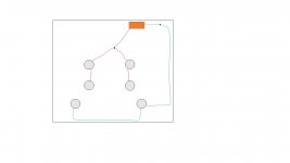
I made a few quick drawings: Orange Block is Tranformer, black and blue are secondary leads, green and red are heater wires.
I'm basically wondering if I should run the heater wires along the edge of the chassis when possible, or run them shorter lengths through the middle.
Image 1: running along the outside. If I do this, I'll need to cross signal over the heater wires.
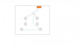
Image 2: here, I could run the signal in the sides and avoid the heater wires
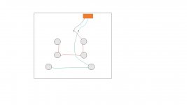
Image 3: Is this a better layout?
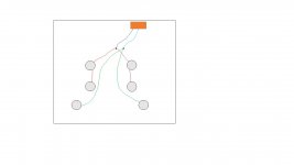
Image 4: This would leave me the most space to enter chassis while avoiding the heater wires.
Thanks for the help!
It took me a while to get everything started, but I'm starting to see the end (maybe not see it yet, but I can tell it's there).
Eli Duttman has been amazingly helpful and generous with his time in helping me built my amp! Power supply is up and running and all the parts are in hand.
But as more general questions have come up, I was hoping a few could be answered here so I don't use too much of Eli's time and abuse his generosity.
I'm wondering about the heater wiring layout: I've got two secondaries off the transformer I'll be using.
I made a few quick drawings: Orange Block is Tranformer, black and blue are secondary leads, green and red are heater wires.
I'm basically wondering if I should run the heater wires along the edge of the chassis when possible, or run them shorter lengths through the middle.
Image 1: running along the outside. If I do this, I'll need to cross signal over the heater wires.
Image 2: here, I could run the signal in the sides and avoid the heater wires
Image 3: Is this a better layout?
Image 4: This would leave me the most space to enter chassis while avoiding the heater wires.
Thanks for the help!
Attachments
you may have to replace the output transformers for 8 ohms
Yep!
Eli was amazing and set me up with plans inspired by the Sherwood S5000. Basically all new except the power tranformer and the chassis.
- Status
- This old topic is closed. If you want to reopen this topic, contact a moderator using the "Report Post" button.
- Home
- Amplifiers
- Tubes / Valves
- Zenith 7b31 EL84 Tube Amp Low Volume