The value used by Niklas in his sim: 319.somethingWhat do you take the unloaded secondary voltage as being?
simon7000,
recalculated from the datasheet to adapt for 230V primary that would be Vp~320V/~Vpp 640V
In Sweden the mains must be within 230 volt ±10% 50 Hz, better than that in reality, have never measured over 238V and never below 218V...In my house most times 230.2...V rock steady.
So I think the sf4007 diodes 1kv rating would be enough by quite some margin, but I could be wrong.(very experianced in beeing wrong ) Please elaborate if you feel it's so.
In ltspice, I made the clumsy and not very correct approximation of a transformer secondary with just a sine voltage source with some source resistance. See attachment.
But it gives fairly accurate results according to psud II, within decimals or at least a volt when comparing so I thought it is good enough.
recalculated from the datasheet to adapt for 230V primary that would be Vp~320V/~Vpp 640V
In Sweden the mains must be within 230 volt ±10% 50 Hz, better than that in reality, have never measured over 238V and never below 218V...In my house most times 230.2...V rock steady.
So I think the sf4007 diodes 1kv rating would be enough by quite some margin, but I could be wrong.(very experianced in beeing wrong
In ltspice, I made the clumsy and not very correct approximation of a transformer secondary with just a sine voltage source with some source resistance. See attachment.
But it gives fairly accurate results according to psud II, within decimals or at least a volt when comparing so I thought it is good enough.
Attachments
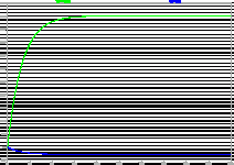
A quick check of Andrews idea, works as predicted...Nice, slow ramp-up of voltage.
Very low ripple indeed even without shunt regulation...Perhaps this will be a little fiddly to adjust as the ccs setting has such an impact on output voltage? But simplicity and performance-wise this is good, could even strip away some of the filter sections I think.
Very low ripple indeed even without shunt regulation...Perhaps this will be a little fiddly to adjust as the ccs setting has such an impact on output voltage? But simplicity and performance-wise this is good, could even strip away some of the filter sections I think.
Attachments
In the examples I gave, all those having a ripple rejection network (C1 R5 in the last one) inherently provide a ramp at power up.Still, it has too low control against over-voltage in case the output current is 0, and the ramp-up is much faster with the ccs set to higher values as 60-something mA.
The slope can be controlled by modifying the capacitor value.
simon7000,
recalculated from the datasheet to adapt for 230V primary that would be Vp~320V/~Vpp 640V
In Sweden the mains must be within 230 volt ±10% 50 Hz, better than that in reality, have never measured over 238V and never below 218V...In my house most times 230.2...V rock steady.
So I think the sf4007 diodes 1kv rating would be enough by quite some margin, but I could be wrong.(very experianced in beeing wrong) Please elaborate if you feel it's so.
In ltspice, I made the clumsy and not very correct approximation of a transformer secondary with just a sine voltage source with some source resistance. See attachment.
But it gives fairly accurate results according to psud II, within decimals or at least a volt when comparing so I thought it is good enough.
In the US the voltage is slowly being raised to improve efficiency. so what use to be 110 is now called 120 and is often 127! Soon to be 132.
Safety analysis is often lacking because electronic parts are extremely good at quality control. So a 1000 PIV diode will almost always handle 1000 volts but probably not 1100.
If the transformer is rated at 230 volts on the secondary it is reasonable to allow for 10% high line input. There is also what is called transformer regulation. Since a transformer has to provide rated voltage at a rated current and has some internal losses when unloaded the voltage will rise. A good transformer will rise by 10% a less costly unit may rise by 30%. You seem to understand the difference between RMS and peak voltage (1.414 x greater) and that the diode charges a capacitor to the peak voltage and then sees on it's input the negative peak thus doubling the peak voltage.
So a 230 volt AC rms secondary voltage could be 230 x 1.414 x 2 x 1.1 x 1.3 = 930 volts. Still withing the rating of the 1N4007. However a line surge caused by a nearby lighting strike would push us past this.
In this case the most likely voltage regulation of the transformer is 10% so the expected normal line voltage would be 230 x 1.414 x 2 x 1.1 = 715 volts.
A normal safety factor when using high quality products is 1.5 (Goes up to 10 x for high risk designs!) That would be 1073 volts for these diodes, a bit more than the rating. As the diodes are so cheap it would be prudent to use two in series with small capacitors across them to distribute any transient spikes.
The diodes most likely will work solo but experience premature and "unexplained" failure from even a small surge.
So the issue is not design theory but design practice. I suspect you do not use 1/4 watt resistors actually at 1/4 watt! (Where distortion is critical limit them to about 1/16 watt. See Linear Audio Vol. 1)
Your theory is spot on. A few more explosions and you will be experienced in the practical.
Last edited:
simon7000,
thanks for your effort to help.
In this case the 230V (rms secondary) is really the unloaded voltage, so you see the diodes are well within margin.
Seems antek uses other method for specs than I'm used to. Have mostly been using general purpose toroids before and they are always speced at rated current/voltage accompanied with a regulation number.
Antek spec the unloaded voltage...Just checking the tests sections in their datasheets confirms this.
simon7000,
thanks for your effort to help.
In this case the 230V (rms secondary) is really the unloaded voltage, so you see the diodes are well within margin.
Seems antek uses other method for specs than I'm used to. Have mostly been using general purpose toroids before and they are always speced at rated current/voltage accompanied with a regulation number.
Antek spec the unloaded voltage...Just checking the tests sections in their datasheets confirms this.
Great, I get you have safety factor with a 34 volt margin to spare! What size fuse are you using?
- Status
- This old topic is closed. If you want to reopen this topic, contact a moderator using the "Report Post" button.
- Home
- Amplifiers
- Power Supplies
- Zeners for shunt regulation and ground offset


