No problem. Other than I don't know where the hell it is or for that matter what it is nor how to check the voltage to it or what the voltage should be. I am definitely going to need a bottle of Tequila before the night is over. Any help would be greatly appreciated. Not with the tequila but with the questions I have about this Q2. I have reached the limits of my expertise.
Dazed and confused,
Tom Wild [WILD1]
Dazed and confused,
Tom Wild [WILD1]
Check ALL op-amps - this is usually what blows up in the regulator circuits of these amps. Don't ask me how I know this..
Ok so you have experience ...LOL
I'll step back which one normaly goes?
Why do it the hard way..LOL
This is where we are looking...Link
http://www.arcdb.ws/M100/ARC_M100_schematic2.gif
Regards
M. Gregg
Last edited:
No problem. Other than I don't know where the hell it is or for that matter what it is nor how to check the voltage to it or what the voltage should be. I am definitely going to need a bottle of Tequila before the night is over. Any help would be greatly appreciated. Not with the tequila but with the questions I have about this Q2. I have reached the limits of my expertise.
Dazed and confused,
Tom Wild [WILD1]
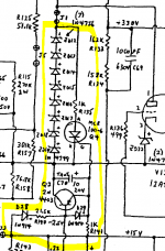
Lets try an easy one first look at R144 see what voltage you have should be -253 its connected to the base of Q2 follow the connection down to bottom of the drawing..
Q2 is under the string of zeners..2n4403
Last edited:
Thanks Greg,
I will find it but I think it is under the lip of the chassis where the zeners are and to get to them I had to basically stand the amp up with face down and go in from the bottom. Not an easy task. Reminds me of working on compact cars, Give me a one ton truck or a John Deere. I will Post when I find it. Kevin do you know the M100s well enough to give me some clues?
Thanks everyone,
WILD1
Okay guys and gals
I found them. One is tucked under the chassis up by the Transformer and one is tucked under the chassis way back by where the 120V line comes in. With the caps there I didn't even know any thing was back there I finally found The Q4 or SCR up by the Transformer and then traced two small wires back to Q2 2n4403. I need a break. Thanks Evette for your input and for that matter thanks to everyone. I will post when I get back.
I found them. One is tucked under the chassis up by the Transformer and one is tucked under the chassis way back by where the 120V line comes in. With the caps there I didn't even know any thing was back there I finally found The Q4 or SCR up by the Transformer and then traced two small wires back to Q2 2n4403. I need a break. Thanks Evette for your input and for that matter thanks to everyone. I will post when I get back.
Can't see the schematic but one use of zeners in a tube amp is to temporarily limit voltages, either on start-up or under fault conditions.
I even did this on one of my Sansui 220 receivers, so when the HT appears the little tubes don't see too much voltage before the tubes warm up and drag down their anode voltages..
I even did this on one of my Sansui 220 receivers, so when the HT appears the little tubes don't see too much voltage before the tubes warm up and drag down their anode voltages..
Okay I am back. There is a different schematic which takes a different approach to the layout and actually gives somewhat differrent voltage values. I think it is a newer version. July 23 1999.It can be downloaded at this site. HiFi Engine | Download Free User/ Service Manuals, Amplifier, Receiver, CD, Tape, Tuner, Video
It means that the SCR is not conducting, which is good - crowbar not activated.
I think you stated that grid voltage was 8.4V and cathode was 8V on the sick amp. If so, you have positve bias which would mean that the tube should draw a LOT of current. However it does not really make sense since this ought to produce even lower plate voltage than the 261V.
But please remeasure these values.
/Olof
I'd start with U6. (Wise to replace U7 since it shares supply rails) In my experience the op-amps blow up frequently and almost nothing else. I used to repair a lot these amps back in the 1990s and the failures were so frequent that I finally refused to repair them anymore.Ok so you have experience ...LOL
I'll step back which one normaly goes?
Why do it the hard way..LOL
<snip>
Tube rolling in the output stage with inferior tubes which fail catastrophically (not the recommended/screened ARC output tubes) will generally result in a lot of destruction due to amp wide power supply transients.
It is very difficult to get the parts out because of the heavy copper and thick pcb. You might consider socketing them with machine sockets. The TL-071 is stable enough for the additional lead inductance to not cause a problem.
- Status
- This old topic is closed. If you want to reopen this topic, contact a moderator using the "Report Post" button.
- Home
- Amplifiers
- Tubes / Valves
- Zeners and voltage regulation