Till -
Just build the circuit and install in your DAC. It will sound wonderful. Try it and you will see.
If you choose to build the Darlington version, try adding a 1kohm resistor from the base of Q1 to ground. This will force Q2 to run in class A and will improve the sound.
Don't worry about your measurements. They are fine. Just install the circuit in your unit and enjoy the nice music you will hear.
If you already have those 431 shunt regulators I say that you must put much more effort in your new ones in order to get better. 431 has 0.6 ohms dynamic impedance which you mosfet regulator won't have. I suggest that you try to simulate so you will be able what you possible can get. A **** Super Regulator would have been a nice upgrade I think.till said:could someone please tell me what would be impedance and ripple figures of his PS in comparison to what i built now?
http://www.geocities.com/yury_g/dac.htm
till said:Thanks for that explanations.
With load resistor i get much less voltage difference.
I built the FET version for +-30V of D1 stage now, and it has much less voltage difference, and ripple i can´t measure with my 5mV / 1cm scope.
The +5V i build bipolar as picture attached. 50 Hz is also not measurable any more with my scope. But i still have a difference between unloaded and loaded. The AD1865 is speced 22 - 26 mA, i will drive 2 of them for balanced. So i loaded the 5V with a 100R resistor for test. The voltage difference i get between unloaded and 100R load is about 16mV: without load ~ 5.20V witth load about 5.04V. Is this critical, should i change something?
Hi Till,
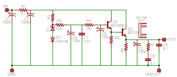
Your schematic looks very similar to this:
http://www.diyaudio.com/forums/showthread.php?postid=181882#post181882
The encircled diode is a red LED.

Originally posted by till
Thanks for that explanations.
With load resistor i get much less voltage difference.
I built the FET version for +-30V of D1 stage now, and it has much less voltage difference, and ripple i can´t measure with my 5mV / 1cm scope.
The +5V i build bipolar as picture attached. 50 Hz is also not measurable any more with my scope. But i still have a difference between unloaded and loaded. The AD1865 is speced 22 - 26 mA, i will drive 2 of them for balanced. So i loaded the 5V with a 100R resistor for test. The voltage difference i get between unloaded and 100R load is about 16mV: without load ~ 5.20V witth load about 5.04V. Is this critical, should i change something?
janneman: The AD load varies between 22 and 26 mA you say, so assume a load of 24mA plus the standing 100mA and set you output to 5VDC with that load. That will be quite sufficient.
And I have to agree with Charles Hansen: While this thread has concerned itself with measureable specs, which are, (and I feel strongly about that), very important to get a good quality reproduction, at this point you may as well go ahead, built it, and see how it sounds. If you're happy, you're happy.
Jan Didden
Thanks for all the advice.
First i made the +-5V regulators as last schematic, with only one rail connected to transformer everything was fine. Both connected gave me ~10mV ripple, dependend how close i stay to the circuit, less if i touch transformer with hand, like a ghost in the circuit.
Now i added CRC filtering before and ripple is not measurable what means below 1mV p2p whats the end of what i can see with the scope. The variation with load increased to about 20mV between 0R and 100R load. Both extrema are still inbetween 4.75 and 5.25V warm and cold, so it should at least not damage the DACs.
I compared with a 7805 at same powersupply, connected after first 1000uF cap. The 7805 shows also no measurable ripple with and without load, but with load there is much HF garbarge to see with the fast scope (TEK7904) the slow scope 25Mhz TEK7313 shows nothing.
http://www.geocities.com/yury_g/dac.htm
Also the current sourced by the DACs I out signal is +-1mA, not really much i think.
The 22 - 26mA figure is stated in the Analog Devices datasheet http://www.analog.com/UploadedFiles/Data_Sheets/177648882AD1865_0.pdf as Typ and max I+ and I- of analog supply. No min. value give. I don´t know if there is no minimal value, or if it is not of interest for them so they don´t tell.
First i made the +-5V regulators as last schematic, with only one rail connected to transformer everything was fine. Both connected gave me ~10mV ripple, dependend how close i stay to the circuit, less if i touch transformer with hand, like a ghost in the circuit.
Now i added CRC filtering before and ripple is not measurable what means below 1mV p2p whats the end of what i can see with the scope. The variation with load increased to about 20mV between 0R and 100R load. Both extrema are still inbetween 4.75 and 5.25V warm and cold, so it should at least not damage the DACs.
I compared with a 7805 at same powersupply, connected after first 1000uF cap. The 7805 shows also no measurable ripple with and without load, but with load there is much HF garbarge to see with the fast scope (TEK7904) the slow scope 25Mhz TEK7313 shows nothing.
I don´t know if it varies, because i don´t know how a DACs analog part is made. If it is like a Nelson Pass class a amp, there will be no variation. In this case i supect power supply impedance is irrelevant. In case current needed of the DAC analog stage is a direct function of the PCM value written into the DAC, i may have a problem. But to me it looks people don´t build super low impedance power supplys for DACs analog stage.The AD load varies between 22 and 26 mA
http://www.geocities.com/yury_g/dac.htm
Also the current sourced by the DACs I out signal is +-1mA, not really much i think.
The 22 - 26mA figure is stated in the Analog Devices datasheet http://www.analog.com/UploadedFiles/Data_Sheets/177648882AD1865_0.pdf as Typ and max I+ and I- of analog supply. No min. value give. I don´t know if there is no minimal value, or if it is not of interest for them so they don´t tell.
Attachments
It seems the attempt to make a "clean" power supply is like fighting windmills.
I measure one night clean, one night i find something.
With the 25MHz scope its really good for my health, as it looks simply straight.
With the other and the highest gain setting i find some kind of dirty, not easy to trigger, 66MHz about triangular shaped mess.
The great thing: i do see this signal with the probe connected to any of the power outlets of my supply, even with power of / no mains connection. With power on the signal is getting double amplitude or so. With probe connected to anything else i don´t get this signal.
Lets see what i get tomorrow.
Attachments
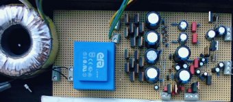
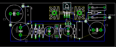
Hi Guys,
i want put a this new regulator in preamp line, but i would to know if i'm ok with my PCB design and if it can have a better sound of my actually regulator?
http://www.diyaudio.com/forums/showthread.php?postid=945744#post945744
Thank you! Maxpou
i want put a this new regulator in preamp line, but i would to know if i'm ok with my PCB design and if it can have a better sound of my actually regulator?
http://www.diyaudio.com/forums/showthread.php?postid=945744#post945744
Thank you! Maxpou
Attachments
- Status
- This old topic is closed. If you want to reopen this topic, contact a moderator using the "Report Post" button.
- Home
- Amplifiers
- Solid State
- zener regulator