Weirdly, I ordered from JLCPCB and they had from @e-fortier original Gerber file and they sent me back a request to change similar to post #492 but I approved them to make the change and ended up with functional boards. I have at least 1 pair left if anyone is interested PM me and I'll send them out USPS only.
As a side note....
If I did PCB design I'd probably put two three-watt resistors in parallel for the bias resistor rather than one 3-watt , which got hot and melted the cheap clip-on probes from my multimeter (not that I would have thought of this during design). Of course, I left them on for an hour or more. 5 watt is a good idea too. I might also order a multi-turn pot for the bias although the single turn does work. (I biased at .75 volts)
Last edited:
...then..Thanks Stan, I’ll go with 0.5R, 5W 👍
What is the number of manufacturer or Mouser for this R1 resistor?
Is this wirewound resistor proper?
https://www.mouser.kr/ProductDetail/Vishay-Dale/NS005R5000FB12?qs=d8Z78VFXGhkUcvPP/DEc/w==


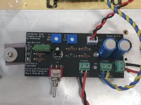
PCB by e_fortier
Power supply : 18VDC, 3A SMPS
R1 : 0.5R, 5W https://www.mouser.kr/ProductDetail/Vishay-Draloric/AC05000005007JAC00?qs=R4/Aj8xQbdXW%2BmVd5kK40A==
Inductor : CH-4 (Bel Signal Transformer, 70mH, 600mOhms DCR)
C2, 3 : 3300uF, 25V
When I turn the switch on, the power LED blinks.
Power supply : 18VDC, 3A SMPS
R1 : 0.5R, 5W https://www.mouser.kr/ProductDetail/Vishay-Draloric/AC05000005007JAC00?qs=R4/Aj8xQbdXW%2BmVd5kK40A==
Inductor : CH-4 (Bel Signal Transformer, 70mH, 600mOhms DCR)
C2, 3 : 3300uF, 25V
When I turn the switch on, the power LED blinks.
Attachments
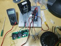
I changed smps to linear psu 17.4VDC.
I turned P1, P2 pots to full counterclockwise.
I switched it up ... then voltage of R1 was about 2.0 VDC.
...and my BOM https://docs.google.com/spreadsheet...XHMWGuYM4kkblgmK2L_q9G52M/edit?usp=drive_link
I turned P1, P2 pots to full counterclockwise.
I switched it up ... then voltage of R1 was about 2.0 VDC.
...and my BOM https://docs.google.com/spreadsheet...XHMWGuYM4kkblgmK2L_q9G52M/edit?usp=drive_link
Attachments

Hi
As I mentioned earlier, P1 is connected the wrong way. You must put it fully clockwise to have minimal bias then turn it gently counterclockwise to slowly increase bias up to about 1.5A to get about 0.75Vdc across R1. Keep me posted.
You can put back your SMPS if you wish.
Eric
As I mentioned earlier, P1 is connected the wrong way. You must put it fully clockwise to have minimal bias then turn it gently counterclockwise to slowly increase bias up to about 1.5A to get about 0.75Vdc across R1. Keep me posted.
You can put back your SMPS if you wish.
Eric
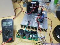
@e_fortier Thank you!
I started adjusting P1 from full clockwise and got 700mV 1.4A bias.
I started adjusting P1 from full clockwise and got 700mV 1.4A bias.
Attachments
- Home
- Amplifiers
- Pass Labs
- Zenductor