8 opamps?!Thank you so much for a proper answer.
it is about a Teac player with 2 AD1862 per channel. between the chips and xlr's you will count 8 opamps per channel! wich is damaged now and I must do something for the babe now. this ZEN i/v seems the right one. hope I can make it works again.

Really you will love the results from this Zen converter!
Very soonis there any pcb?
or any photo of the Zen I/V on a stripe board? appreciate if a nice gentleman could upload one or two!
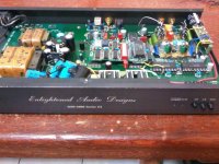
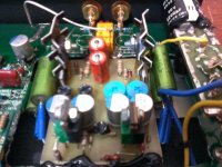
At least photos from my Lateral MOSFET implementaion
The PCB is hand made (in 2015!) **CAD free zone***
Sorry the low resolution, I really need an new camera with macro.
The PCB is hand made (in 2015!) **CAD free zone***
Sorry the low resolution, I really need an new camera with macro.
Attachments
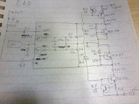
My schema...
Definitely I'll end up winning the DIYA prize for more poorly readable scheme from the earth ...
PROCEDURES for ADJUSTING:
Remember: the adjustment should be made with the converter without being connected to the DAC.
Adjust the two pots of 2 MOSFETs to get 15V around the drains and ZERO volt in sources (output of the DAC). After that you connect this to DAC chip and enjoy the sound!
The resistor 75R serves as an RF outlet for the DAC.
I decoupled the filter capacitors with good RF capacitors.
Use a good ground plane in the PCB or use a copper foil to the ground (I used both).
Attachments
My schema...
Definitely I'll end up winning the DIYA prize for more poorly readable scheme from the earth ...
PROCEDURES for ADJUSTING:
Remember: the adjustment should be made with the converter without being connected to the DAC.
Adjust the two pots of 2 MOSFETs to get 15V around the drains and ZERO volt in sources (output of the DAC). After that you connect this to DAC chip and enjoy the sound!
The resistor 75R serves as an RF outlet for the DAC.
I decoupled the filter capacitors with good RF capacitors.
Use a good ground plane in the PCB or use a copper foil to the ground (I used both).
Nice! Something to try on my next project.
I may use it on a dual PCM1704 DAC too. Any value need to be changed? Since the output current of PCM1704 is 1.2mA, compared to PCM63's 2.0mA.
People with low current output DAC chip can opt to use this I-V with higher voltage, or use the original with a preamp (I prefer to eliminate pre if possible). In supply, change the regulator for more regulated voltage (if using my regulator you can change the zener value), and the raw +/-B will need at least 10V spare to correctly and smootly operate the CCS (so, +/-55V input to +/-45V output). The supply transistors will need an PCB-style heatsink.T...... You can use a higher supply voltage, which will enable the use of a larger value of drain resistors (to keep the drain voltage to 15V), obtaining an increased gain.
Compared to the PCM63, which has +/-2mA output (approx. 1Vp or 0.7Vrms), you will get half the output voltage using the AD1862 ...... So you can use +/-45V to obtain 2k into drain resistors and double gain to compensate the AD1862, for example.
People with low current output DAC chip can opt to use this I-V with higher voltage, or use the original with a preamp (I prefer to eliminate pre if possible). In supply, change the regulator for more regulated voltage (if using my regulator you can change the zener value), and the raw +/-B will need at least 10V spare to correctly and smootly operate the CCS (so, +/-55V input to +/-45V output). The supply transistors will need an PCB-style heatsink.
Thanks for the information.
First: is good to have at least some 8~9V on the MOSFET drains (15V is better), because is necessary to be outside the region where the internal capacitances are highly nonlinear. And is necessary to have some health current in order to maintain good transconductance in converter MOSFETs. So this results in low voltage into output resistors and so low ohmic value and low gain. In practice is better to maintain the minimum +/-30V. The gain with 4mA DAC will be very goodhi all
i have 4mA DAC and want to build the ZEN IV.
first: can i do it with 15+- supply?
sec: i want to connected the zen to my active filter (base on B1), do i need buffer before the filters?
thanks
Second: These I/V converter have ~500R of Z output, so this will change the filter behavior so is good to use some buffer like the B1. Or simulate the filter to compensate for it (not a very good idea in most cases).
- Home
- Amplifiers
- Pass Labs
- Zen I/V Converter