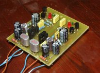
Well, I've built it. The actual SEN is only one tenth of the PCB  , the rest are two shunt regulators. I used two separate transformers, and I was having trouble with large amounts of hum, buzz, distorsion, etc., but that was solved after adding of 100R resistors on gates going to the ground (thanks for the tip
  )
)
I still have some "buzz" on higher volume levels, but I thing that the problem is with close proximity of transformers, I will rearrange them. It is sounding good so far, the voltage on regulators is 17.5 V, I will experiment with higher voltages, for with these transformers I can go as high as 21 V regulated.
Thanks again for everything
, the rest are two shunt regulators. I used two separate transformers, and I was having trouble with large amounts of hum, buzz, distorsion, etc., but that was solved after adding of 100R resistors on gates going to the ground (thanks for the tip )I still have some "buzz" on higher volume levels, but I thing that the problem is with close proximity of transformers, I will rearrange them. It is sounding good so far, the voltage on regulators is 17.5 V, I will experiment with higher voltages, for with these transformers I can go as high as 21 V regulated.
Thanks again for everything
Attachments
Ah, once again I forgot to write something.
This is off course only one SEN PCB made for personal use. I do not intend to "manufacture" it or anything like it. It's not even a "real" PCB actualy, I just drilled some more holes in spare space of the shunt PCB and connected the JFETs with wires
This is off course only one SEN PCB made for personal use. I do not intend to "manufacture" it or anything like it. It's not even a "real" PCB actualy, I just drilled some more holes in spare space of the shunt PCB and connected the JFETs with wires
- Home
- Source & Line
- Digital Line Level
- Zen -> Cen -> Sen, evolution of a minimalistic IV Converter