but that wouldn't be any fun. I've already got plenty of current feedback opamps, the idea is just to play with it and see if i can make something cool with these bags of bc550/60 i have that i will never use all of.
and as you mention in your post AD844 has inputZ of ~65R, which is a waste of time with sabre, well at least without the good natured harmonic of jfets or other more suitable opamps it is. i don't generally even like bipolars, but just thought your cct could be cool to play with.
and as you mention in your post AD844 has inputZ of ~65R, which is a waste of time with sabre, well at least without the good natured harmonic of jfets or other more suitable opamps it is. i don't generally even like bipolars, but just thought your cct could be cool to play with.
Last edited:
May I suggest Digikey Part No. PLK1182-ND too?Sorry, the link is not very specific.
This is the part No. at Digikey : PLK1273-ND
There are other from Epcos for example. just make sure the choke can cary enough current.
Especially in a shunt regulator that draws a lot of current.
99mH (instead of 100) same current rating, Rdc 2.7 (instead of 2.5), but much less expensive: 1.79 + VAT instead of 4 Euro ea.
Vertical structure (footprint 27.5 x 18 mm) instead of horizontal (28.5 x 29 mm)
Another advantage to the lower-VA transformers is lower interwinding capacitances, for similar transformer types. Although the datasheets rarely give this number, I measured it for an Avel Lindberg 18VA part I had as about 24pF, from one secondary to one primary winding. Although that doesn't sound like much, it would be nicer smaller.
> the idea is just to play with it ...
I actually have a half-finished layout, but as Joachim said, the BC5x0s are best at 4mA bias.
This is way to low for the ES9018 unless you start paralleling them.
Then the layout and thermal management becomes too messy.
Of course you already have the circuit.
So you can always start bread-broading if you are so determined to try.
")
Patrick
I actually have a half-finished layout, but as Joachim said, the BC5x0s are best at 4mA bias.
This is way to low for the ES9018 unless you start paralleling them.
Then the layout and thermal management becomes too messy.
Of course you already have the circuit.
So you can always start bread-broading if you are so determined to try.
Patrick
I was looking at BF862. With its higher Idss an lower capacitance, can it be a good a good canditate for SEN ?
IMO it should work well, but as a SOT23 has lower permissible power dissipation, is difficult to heatsink, and is cumbersome to breadboard. So the drain-source voltage needs to be lower. However the lower C suggests the possibility of additional paralleling.
I've been inspired by this topology, and the advantages conferred by the floating supply in particular, to investigate some less-minimalist versions. The 862 figures prominently --- we will see if it is worth the trouble. For some other remarks on the 862 see Scott Wurcer's article in Linear Audio vol. 1, and also Popa's experiences with paralleling them and controlling the tendency to high frequency oscillations (his website articles are referenced in his piece in that same issue).
Brad
Last edited:
In simulation at least it is worst than 2SK170, but that can be an artifact of the Spice models we were using.
In practice you have two slight problems -- matching and thermal coupling SOT23 devices.
Both are solvable, but since 2SK170 can still be had for little money, it is better choice for DIY.
Patrick
In practice you have two slight problems -- matching and thermal coupling SOT23 devices.
Both are solvable, but since 2SK170 can still be had for little money, it is better choice for DIY.
Patrick
In simulation at least it is worst than 2SK170, but that can be an artifact of the Spice models we were using.
In practice you have two slight problems -- matching and thermal coupling SOT23 devices.
Both are solvable, but since 2SK170 can still be had for little money, it is better choice for DIY.
Patrick
I found similar results in simulation, including ones from more elaborate topologies, but I think most of the SK170 models out there are optimistic about output conductance (the models are too low compared to the datasheet curves). Ditto the models for the dual that resembles two SK170, the SK389, which otherwise has at least the matching (and I have about 900 of
).Brad
3rd Party PCBs based on my published Circuits
Someone asked me by PM whether he has my permission to use my CEN/SEN circuits in a custom PCB of his own design, and whether I would give my blessing for a GB for his PCB.
I already replied to him by PM, but I think I also want to make a stand on the issue openly.
Firstly I thank him sincerely for asking, and for his interests in my circuits.
For someone who has more than 100 patents and patent applications, and knows a bit about patent laws worldwide, I am fully aware that in publishing the circuit in Linear Audio, I have made the circuits public property and have no further intellectual rights.
So in that sense, anyone can copy my circuits (whether for his own use or otherwise) without fear that I shall take legal action against him.
Whether it is morally the right thing to do, I leave it to the individuals to judge for themselves.
I shall, in principle, NOT give my blessings to ANY GBs for PCBs or the like, based on any of my published designs, for the following reasons :
a) I do not want to give the impression that I endorse such actions in any way.
b) I do not intend to spend time checking the quality of the PCB layout, giving it my approval, and therefore invite false interpretation that I shall also support any trouble shooting, etc., especially in cases where I have doubt that the PCB layout person fully understands the functioning of the circuit, and what is important and what not.
c) I do not want to encourage the use of my name and the names of my designs in undertakings which has nothing to do with me, especially when I have already made such PCBs and important associated parts available, to the quality that I demand.
I welcome you wholeheartedly to experiment with my circuits, and make PCBs for your own specific use, as long as there is no implication of any connections to me. If you have trouble finding a PCB shop that does single or small quantity prototypes, Jan Didden of Linear Audio knows a very good source based in Europe. Failing that, you can also contact me and I shall make use of our facilities to get a couple made for you, at cost.
But no, I am sorry that I shall NOT endorse any public sales actions of PCBs based on my designs, whether profit making or not.
If you wish to do so, it is entirely your own action and it has no connections to me whatsoever.
I hope I have made my position crystal clear. And my apologies that I am not more forthcoming.
Best regards,
Patrick
.
Last edited:
clear, to the point and completely reasonable. the time you have invested in supporting this and other projects around the forum is obvious and for sure you don't want to land yourself in the position that salas is in with a certain other.... massive (in size and number) regulator pcb and its GB participants who regularly invade the legit thread asking for support.
now sit back and wait for the hundreds of requests for 2 pcbs =)
I wouldn't think the bf862 would be much fun particularly in the SEN, thermally coupling 4 of them tightly, while possible would be a complete pita while also providing them with the increased current/dissipation capability
now sit back and wait for the hundreds of requests for 2 pcbs =)
I wouldn't think the bf862 would be much fun particularly in the SEN, thermally coupling 4 of them tightly, while possible would be a complete pita while also providing them with the increased current/dissipation capability
Last edited:
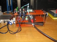
So, I realized that I posted my results in the GB, maybe here is more interesting. Starting this project I had mail two goals:
1) Having a simple platform to evaluate nuances in sound.(Kind of hear training)
2) Putting the basis of a light weight portable DAC.
As this is a source I decided to use mainly headphones, so I can escape family constrains. I needed a SE headphone amp and the O2 is a three hours project, once you have everything you need on the table.
The DAC is an AD1865, I connected the current output to a LEMO connector, the best I had in hand. Various version of the Xen can be swapped in few seconds.
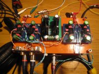
Assemble the boards is easy; I used this order:
1) SMD resistors (pad side only)
2) Jumper. I left the leads of the jumper very long, as I have Vref boards, and for the AD1865 the reference needed to be grounded. So I use the excess of lead to connect the Vref pad.
3) Through hole resistors.
4) Film caps.
5) Not all the JFET have the same size, you can see it even in the data sheet. Some of them are lose in the heatsink some are very tight. The tight one need to be fitted in the heatsink before soldering. I put all the JFET, and solder only one leg for each fet. Then check again and adjust the position. When everything was aligned I soldered the remaining legs.
6) Electrolyte caps.
I like the sound: the CEN for me is a bit more elegant, but the SEN has a bit better bass. I use my wife as distortion meter (I envy that she always manage to pick the setup that measure less distortion, blindly), and she picked the SEN, describing it more precise.
I was supposed to receive a new scope today, so I postponed any measurements. I found out that my scope from UK, arrived in Tokyo on Saturday, and took a detour first to Germany, then to India. It is now in China. It's not a joke !!!. So, long story short, I will have to wait a bit more to make some measurements.
I am also playing around with the current mirror and the BJT version, but I still need a bit of work.
Once everything is OK with the AD1865, I plan to test it with the ESS9018. Beside the Vref, I see another problem: in the article it is stated that the circuit can swing 25 % of the total current. So best case scenario we will have 20mA for the SEN so 5mA swing, but the ESS9018 has 16mA output. We can add another quad, but not on this board. I am sorry if this problem has been already solved.
More listening tonight.
Best Regards,
Davide
1) Having a simple platform to evaluate nuances in sound.(Kind of hear training)
2) Putting the basis of a light weight portable DAC.
As this is a source I decided to use mainly headphones, so I can escape family constrains. I needed a SE headphone amp and the O2 is a three hours project, once you have everything you need on the table.
The DAC is an AD1865, I connected the current output to a LEMO connector, the best I had in hand. Various version of the Xen can be swapped in few seconds.
Assemble the boards is easy; I used this order:
1) SMD resistors (pad side only)
2) Jumper. I left the leads of the jumper very long, as I have Vref boards, and for the AD1865 the reference needed to be grounded. So I use the excess of lead to connect the Vref pad.
3) Through hole resistors.
4) Film caps.
5) Not all the JFET have the same size, you can see it even in the data sheet. Some of them are lose in the heatsink some are very tight. The tight one need to be fitted in the heatsink before soldering. I put all the JFET, and solder only one leg for each fet. Then check again and adjust the position. When everything was aligned I soldered the remaining legs.
6) Electrolyte caps.
I like the sound: the CEN for me is a bit more elegant, but the SEN has a bit better bass. I use my wife as distortion meter (I envy that she always manage to pick the setup that measure less distortion, blindly), and she picked the SEN, describing it more precise.
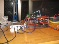
I was supposed to receive a new scope today, so I postponed any measurements. I found out that my scope from UK, arrived in Tokyo on Saturday, and took a detour first to Germany, then to India. It is now in China. It's not a joke !!!. So, long story short, I will have to wait a bit more to make some measurements.
I am also playing around with the current mirror and the BJT version, but I still need a bit of work.
Once everything is OK with the AD1865, I plan to test it with the ESS9018. Beside the Vref, I see another problem: in the article it is stated that the circuit can swing 25 % of the total current. So best case scenario we will have 20mA for the SEN so 5mA swing, but the ESS9018 has 16mA output. We can add another quad, but not on this board. I am sorry if this problem has been already solved.
More listening tonight.
Best Regards,
Davide
Attachments
I am looking at my ES9018 datasheet Rev 1.1 (2009) p.25.
For XLR output, they use an Riv of 680R per phase for 2 channels.
Assuming normal XLR output level of 2Vrms per phase, that corresponds to 8mA pk-pk, or +/-4mA.
So 16mA bias will just do (+/-25% swing).
As in all Class A circuits, the higher the bias, the less the distortion.
But as described in the article, the distortion mechanism here is different due to the separate current loops.
Perhaps a simple SPICE simulation will tell more.
Or just try and (ask you Mrs. to) listen.
Patrick
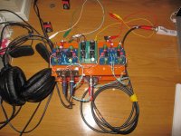
I am having fun with this thing, both on the electronic point of view and anthropological .
I added a new layer to the building with the CEN BJT as posted in post 62, using BC550/560.
I moved the setup to my office, collecting impression and had some interesting feedback passing from one type of IV to the other. Here is one, playing Diana Krall (96kHz):
CEN BJT: "I feel like I am sitting in the recording studio, very rich sound"
Switch to SEN JFET: " Oh, now she is singing right in front of me"
Patrick, I have to find out if my wife can do FFT as well.
Davide
.I added a new layer to the building with the CEN BJT as posted in post 62, using BC550/560.
I moved the setup to my office, collecting impression and had some interesting feedback passing from one type of IV to the other. Here is one, playing Diana Krall (96kHz):
CEN BJT: "I feel like I am sitting in the recording studio, very rich sound"
Switch to SEN JFET: " Oh, now she is singing right in front of me"
Patrick, I have to find out if my wife can do FFT as well.
Davide
yeah i found a nice discovery, looking through my boxes for parts for the SEN this morning i found a set of 4 x 0.01% 680R tx2575 that i bought some time ago for the TP IVY, but as i never ended up using the IVY and on my other IV i used the ASMP smd zfoils, they sat here untouched =) i think i will still use the bulk foil trimmers initially, but it was a happy discovery indeed! the swing is 3.05v @ 3.903ma p2p with AVCC of 3v3, but i'm using a higher voltage for AVCC (3.6v) as it results in better DNR, although how much it improves past 3.4-5v is unclear
i'm using some 10.9ma k170
i'm using some 10.9ma k170
Last edited:
hmm, i'd prefer not to have to buy more semis if i can avoid it, i'll try the k170 for now and add some k369 with my next utsource order. i was going to ask about Zin actually ie paralleling more fets, but it seems this may not actually provide the usual benefit with this circuit
There has been a lot of discussions about Zin for ES9018. I have not tried, so I would not want to comment.
BUT if you do want low Zin and run +/-4mA in 2-channel mode, then I would certainly want to 4x matched 2SK369V per single ended SEN Vref, with about 30mA total bias.
And you should stock up Toshiba devices while you can still get them.
Patrick
BUT if you do want low Zin and run +/-4mA in 2-channel mode, then I would certainly want to 4x matched 2SK369V per single ended SEN Vref, with about 30mA total bias.
And you should stock up Toshiba devices while you can still get them.
Patrick
...And you should stock up Toshiba devices while you can still get them.
Patrick
Amen! So many semis disappearing. And not just JFETs --- John Addis recently pointed me towards some wonderful bipolars with high breakdown and low capacitance, useful in Boxall and Aldridge circuits*. They are long gone and scarce, even though in SM packages and not that old. Why? No more demand for video CRT drivers
Brad
*translation: Larsen-Baxandall-Swallow and Hawksford; see my recent posts in a Baxandall thread --- the origination dates have been pushed back by some recently discovered documents.
yeah i'm well aware of the zin issue, its why i never bothered with the zen, but what i'm saying is, i'm not going to rush out, pay express international shipping on a small order of jfets just so i can shave a tiny amount off the zin, i havent checked the numbers, how much higher is the gM really? its still a jfet. this IV stage will NEVER be ideal for 9012/18 for that reason if i was going for ultimate measured performance with this dac in that regard, ide be going with the bipolar version.
i will get them, but i'm not in a huge hurry. i do vaguely remember seeing the recommendation now a while ago. the thing is, i really dont need another pile of jfets, is anyone selling matched? i simply dont have the time or desire to buy and sort another 100 jfets only to use 16 (youde understand if you saw my workshop bench at the moment)
i will get them, but i'm not in a huge hurry. i do vaguely remember seeing the recommendation now a while ago. the thing is, i really dont need another pile of jfets, is anyone selling matched? i simply dont have the time or desire to buy and sort another 100 jfets only to use 16 (youde understand if you saw my workshop bench at the moment)
Last edited:
- Home
- Source & Line
- Digital Line Level
- Zen -> Cen -> Sen, evolution of a minimalistic IV Converter