Hello everyone,
This is my first post directed to those with experience diagnosing SMPS faults. I know there are a few of you out there.
Quick intro:
I'm qualified electronic tech.
I have a friends audio mixer that I volunteered to take a look at when he said it was dead. SMPS fault.
I'm much more familiar with linear PSUs
I've given myself a crash course in SMPS so I have a fairly good understanding.
I have ALL schematics! 3 pages attached. And it's a very good quality mixer, 15 years old.
The PSU initially had a fried L6561 controller.
In my testing lots of the SMPS is working - but it has an over voltage condition that I'm trying to diagnose. So the regulation isn't working - hence it's frying the L6561 (3 so far...but I bought spares and I now have a VARIAC).
No "be careful warnings" needed.
How to diagnose the feedback and work out why it's not regulating is where I'm at? Shunt regulator (431) - Optocoupler etc. The biasing around the 6561 I don't entirely understand.
What sets the 32v rail limits?
Is the orange wire connection in the secondary feedback loop significant & any purpose for regulation?
So far I have:
Changed the MOSFET & TIP50.
Done the v2 mods as noted in the schematic.
Checked the 1u/63v C79 cap (near the OPTO). C & ESR read OK.
Changed the OPTisoltaor even though I removed it and it bench tested under power ok.
(I have a replacement 431 coming)
Can't measure a dud diode anywhere.
I saw a note line saying a SMPS can go over voltage with low line voltage. Basically I'm over voltage at only 30 VAC line voltage but I daren't turn up the line voltage any more. It's rated at 100-240v in.
At 30v in I'm getting +40v and -29v out. And 19.2v on the L6561 - which I'm watching very closely to not exceed. I find it a bit odd that I'm getting such a mismatch in the rail voltages. 11v difference. Maybe due to different loads though...?
Concerns:
The 4 x 3300 caps on the secondary I'm going to de-solder tonight and check ESR. Can't check C as too big for my instrument - not too happy about that. Will check behavior with the DMM.
I may be well off track too I realise.
Advice for a procedure to isolate & eliminate would be useful esp. around the feedback loop.
Thanks,
Attachments
Go back to basics! If the -32V is incorrect, check its monitor/control point on the 431 programmable zener diode.
L6561? What and where is that?
The feedback is controlled by 6881 on pin 1 of U4. That is basically all there is to it. Over current is detected on pin 4 of U4. Take a look at the manufacturers datasheet on the IC chosen to drive the power supply.
Rule of thumb is replace all components in the control stage.
Hi JonSnell,
Appreciate the reply. Thank you.
6881 is the the Yorkville part # for the control IC which is an L6561 and I've studied the datasheet many times. What exactly I'm looking for at those control points isn't clear to me though - how do I know what's right and not right? I'm not saying that you'd know.
There has to be a component fault under my nose that I'm missing so I will heed your "rule of thumb" advice - that's a plan. And that will be quicker than pondering what to change next even though the components that I've measured so far check out OK.
Neither rail is regulating BTW.
I'm very motivated to get this working. I've spent such a long time on it.
Thanks again.
All other input welcome until I get this working.
Let me give it a try.
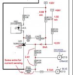
In fact it isn't a + and - 32V regulation, rather a +64V regulator.It senses +64V trough R120 and halve of it via R123.The sum makes the regulation go.So if one part goes down the total goes up and taking with it upwards the supply for the regulator IC.Not so good idea.
The pos and neg commes from the same flyback puls and are therefore equal.Different loads affect both sides.
If there is non the less a difference in pos and neg then it has to do with the conversion of the pulse in DC.Bad D27 and/or C76,C77 or a bad soldering.
Mona
The -32 is the only rail that is regulated as the other rail comes from the same transformer it is likely to be inline with expectations. Don't forget that a low mains voltage will produce spurious results. If the opt is being supplied with voltage then it will increase the DC on the drive and reduce the output.
Q3 is used only for start up. D21 takes over.
Q3 is used only for start up. D21 takes over.
Thank you Ketje - I will take a closer look at those components. The voltage sensing & control circuitry where you've noted is definitely somewhere that I'm suspicious of and I've been studying that area a lot. It's also why I'm a bit perplexed at what influence the orange wire connection has on this sensing circuit through R126/R125. It's connected to collector of Q4 on the Phantom Power section of the Power Amp diag so it seems to be another feedback path to me which could be critical if it ties into the main SMPS R120/R123 voltage divider.
As a side comment - I noticed the voltage regulators on the Power Amp board Q18 & Q19 run pretty hot when I've power this via the VARIAC at only 30VAC which surprised me. Is that a worrying sign of other trouble or a red herring? I replaced the SMPS o/p with 25v DC and separately tested the 32v &-32v rails into the Power Amp and noted no excess current draw so much earlier on so I figured the power amp was running OK and the fan and panel lights all run. I had not noticed the hot regulators back then though.
But I hear JonSnell clearly and others elsewhere when they say that low i/p line voltage can cause odd results.
Yes, JS, I hear your comments too - thank you. I'm acutely familiar now with how this starts up and it does fire up very sweetly via Q3. I crank the VARIAC up checking the voltage on pin 8 of U4 then back it off as the oscillator starts and the o/p come up nicely...even if too much via the AUX winding and D21!
I'm going to do as JS suggests and change a batch of the control components AND I'll look closely at D27 & C76/C77 - I really need to be able to measure those. And I will check solder under an eye glass.
Great to finally share some technical thinking with you guys. This is fix-able.
I will update further.
Thanks from Sydney, Australia.
The orange wire does nothing, only if the sensor detect running to hot (LM3886) it pulls the voltage sensing up making the supply drop (a little).
Q18 gets warm because the +32V is way up.
It not a good idea to enter with low AC voltage.The supply is trying to deliver its normal output (power) from a low voltage witch means high current.As the AC voltage goes up the current drops to get the same power.
Mona
Q18 gets warm because the +32V is way up.
It not a good idea to enter with low AC voltage.The supply is trying to deliver its normal output (power) from a low voltage witch means high current.As the AC voltage goes up the current drops to get the same power.
Mona
Hello to you both. Here's an update and I want to run some thinking past you.
I started to replace the Caps in the control circuit yesterday - 6 so far - with no improvement just yet. I need more time to obtain other components in the next few days.
The difference in the output rails is bugging me and I don't think it should be so different - yes suspicious of D27/28 & C76,77,78,80 which I plan to replace over the w/e. If you look at the secondary voltage sensing circuit around Q20, there seems to be some very precise resistor values in there for some presumably precise voltage control i.i. R126/853R & R125/249R this looks like it's setting the reference voltage for Q29 along with R120/60k4. I make this 1.249v at 64v across both rails. However if I am getting say +37v and -28v is this somehow upsetting the fine balance of this circuit somewhere else? After all pin 2 of U8-A (opt) is pegged to the RET/0v mid point via R121/10k. My point is that IF I were getting say +33 & -33v (as I wind up the i/p VAC) this circuit would be more in balance and it would be happier.
Another question: Q20 is marked as 2v0 but I just can't see where 2v occurs or what this means unless my measurements are off putting. See following:
I wind up the i/p volts to get 65v across + & - rails.
= + 37v & -28v (9v diff...)
With ref to BLUE/neg rail:
top of R126 = 1.23v
P2 U8 = 26.4v
P1 U8 = 27.4v
So the OPT is ON in my opinion - correct?
How does that look to you?
I'm not very familiar with exactly how this shunt regulator and OPT work and I'd really like to more clearly understand it - if you could offer a simple explanation I'd appreciate it. It's obviously supposed to perform a very key function for regulation that I feel isn't working correctly right now.
Thanks,
Good news: found R29 (30K1) o/c. Replaced with 2 x 15k and everything has sprung to life in the feedback loop and it's regulating now however I'm still seeing a worrying imbalance on the rails: the + rail is reading high at +44v vs -30v. The VARIAC is up to about 90VAC. So it's holding firm but I'm now concerned the high + rail is going to stress the +15v regulator on the Power Amp board and it's running a bit too close to the rating of the 50v/3300u caps on the secondary of the SMPS.
I've replaced D7, D8. C10,11,27,16,17,18,19,28.
As well as Q5, U2, C20.
Any suggestions what might be running the + so high?
C22,23,24 no replaced yet.
Jonsnell - your observation was that only the -32V is regulated, so would you still say the +ve reading is not unexpected and maybe this is functioning normally now?
"Any suggestions what might be running the + so high?"
Wel I explained that allready, not very well clearly.
But first, where come all those part names come from? The schematic I found early in this treat is different.The 30k1 you call R29 is R123 for me and the 60k4 is called R120.The same for the other parts, confusing.
Let's go for a second try :lol:
The 44V on R120 (is 44+30V in respect to the -32V line) gives a current of (44+30-2.5)/60.4=1.18mA.
The 30V on R123 gives a current of (30-2.5)/30.1=0.91mA
Those two currents come together at the 2.5V sensing point with a value of 1.18+0.91=2.09mA.That current give the 2.5V drop on the resistors to the -32V line.
The fact that the -32V isn't reached makes the +32V go up the get the 2.5V.
The two output voltages come from the same flybackpulse, if one drops caused by heavy load the other drops too.They copy each other.
Here you have never the less a difference.If the same flybackpulse give different DC then the rectifier part has a difference hence on is defective.In this case the negative side doesn't do its part.
The rectifiers get warm (hot?), not impossible that the negative side has a bad soldering point at the diode.
Mona
Thanks for the detailed reply and sorry for the confusion - the service manual has 2 versions of the SMPS. The 2nd version is differently numbered and has had a few mods including a couple of component changes around Q3 mostly to help startup and R69 10R--->22R.
Re your comments: from your previous reply I did already replace those secondary diodes and caps: D27,D28, C76,77,78,80,72,73,74,75. So the only components I've not yet changed in the secondary which may be contributing to the imbalance in those rails are C81,82,83 - I'll have to replace those today and see if they do balance those rails. Finding R123 (correctly referred to now!) o/c was a major surprise. Not often have I known resistors to go o/c. I started doing some acute voltage testing in that area - based on advice in this thread - including simulating those components on breadboard so I determined something was definitely not connected.
So close now...thank you again.
Update: did replace C81, 82 & 83. Resoldered all transformer joints and other component joints and looked under a glass. All looks good. I also measured the inductance of both secondaries: p8-9 22.69uh, p11-12 21.6uh. Primary is exactly 100uh. Those secondaries to me seems close enough to not indicate a fault causing the voltage mismatch which is still present. I've changed all major components on the secondary side now. Observations:
1. Ran at 100VAC and left on for 5min. D7 & D8 running hot with D7 hotter. And the regulator transistors on the power amp board are hot too. I closed it all up and even tested some music on headphones and seems operational but the box is running hot and I'm sure it will fry itself if I leave it on longer.
2. Earlier I put 25VDC on to each rail in turn and checked the current draw (no mains imput of course). +Ve drawing 190mA, -Ve 236mA. No great overload there.
3. The replacement diodes D7/D8 are BY329-1200 - the best I could get easily. These are classified in excess of the voltage rating and 1A under the current rating of the originals and suited for SMPS. The supply rails were mismatched even before I replaced these diodes so I'm not convinced that these "similar" replacements are causing problems. They will run hotter though with the lower current rating...but with the mixer in a quiescent state they should not run that hot, surely.
So a lot is now working but I do need to get those rails back to + & - 32v.
Not too sure what to try next.
Any further thoughts very welcome.
Thanks,
Steve
Caps C81, 82 and C83 (esp C83 RET to GND) are filtering to ground so RET is isolated as I see it. I totally understand where you're I need to measure - both secondaries to compare. I'm just not convinced I can place the GRD of the scope to pin 9/11 of the transformer and short that to electrical ground.
Do you see that differently?
Do you see that differently?
You're correct! Of course. Sorry. I looked further and can see the RET is connected to chassis at the Power Amp input.
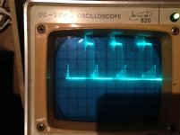
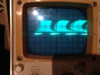
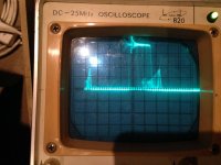
So the scope images are attached. The neg rail isn't pretty at all. It's breaking down big time. The vert scale is 10v.
Maybe a bad cap on the input of the power amp? There's C27 470u/63v, C25 100n/50v and C67 470n/63v C67 all right on that line. Maybe they're next for replacement.
Thoughts?
So the scope images are attached. The neg rail isn't pretty at all. It's breaking down big time. The vert scale is 10v.
Maybe a bad cap on the input of the power amp? There's C27 470u/63v, C25 100n/50v and C67 470n/63v C67 all right on that line. Maybe they're next for replacement.
Thoughts?
Attachments
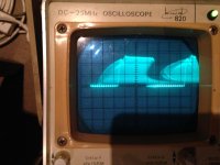
I've been thinking about this more during the evening whilst out.
Such a noisy waveform from the neg secondary could be causing D27 to run so hot - it's switching like crazy. What's causing it though? Can the winding be bad (I'm unsure of symptoms of a winding breakdown and I'm hoping it's not because that's going to be a repair showstopper) or, if I didn't know any history to this SMPS, I'd probably suspect D27 is breaking down. What's more probable? D27 is new though so that's odd. Maybe worth a swap with the original D28 to compare the result. Or I switch over the new D27 & D28 to see if the issue switches rail might give a clue.
Such a noisy waveform from the neg secondary could be causing D27 to run so hot - it's switching like crazy. What's causing it though? Can the winding be bad (I'm unsure of symptoms of a winding breakdown and I'm hoping it's not because that's going to be a repair showstopper) or, if I didn't know any history to this SMPS, I'd probably suspect D27 is breaking down. What's more probable? D27 is new though so that's odd. Maybe worth a swap with the original D28 to compare the result. Or I switch over the new D27 & D28 to see if the issue switches rail might give a clue.
- Status
- This old topic is closed. If you want to reopen this topic, contact a moderator using the "Report Post" button.
- Home
- Amplifiers
- Power Supplies
- Yorkville SM8 mixer SMPS fault - over voltage