Same core area is surely overkill and worse HF performance for the same geometry....wait till the formula man chimes in.......
The solution might that with 2C's and two bobbins one could use a core area that is midway between 1/2 and the same. For example use the HWR 70/32 that has 8 cm^2 core area if I use the HWR 50/32 of the previous example for the shell type. This way the transformer will measure about 8x11x11 cm, so about the same size.
Having longer magnetic path one could make more turns for the same air gap. More turns are also needed for the same inductance because the ratio between core area and magnetic path is worse. However average turn lenght is still shorter at 19.1 cm and surface is about the same at 130 cm^2.
I don't think it is going to be better as 50AE is claiming and you have to make two coils.
The idea of showing this drawing was.
1. If we consider the single bobbin as a sum of two coils with the same windings, it's obvious that due to the increased circumference no matter the equal thickness, the second coil (B) as a larger length per turn, more volume and and more surface area between the windings that would result in more parasitic capacitance Cp and Rdc. The simple formula for a surface area of a ring ; A= pi(r1^2 - r2^2
2. When this bobbin (A+B) is split into two bobbins (A*2), the surface area between the windings of (A*2) will be less than the surface areas of A+B and considering that expression is not linear, it gets worse with increasing coil height.
3. It is TRUE that the surface area between the bobbin and the core doubles on a 2C. I can agree with that, although due to the results of my measurements so far, coil to core capacitance is much less than interwinding capacitance.
4. I'm ending my debate here and thank you for your participation. I will have my OPT wound and in the near future, I'll post my results here.
Last edited:
The idea of showing this drawing was.
1. If we consider the single bobbin as a sum of two coils with the same windings, it's obvious that due to the increased circumference no matter the equal thickness, the second coil (B) as a larger length per turn, more volume and and more surface area between the windings that would result in more parasitic capacitance Cp and Rdc. The simple formula for a surface area of a ring ; A= pi(r1^2 - r2^2
2. When this bobbin (A+B) is split into two bobbins (A*2), the surface area between the windings of (A*2) will be less than the surface areas of A+B and considering that expression is not linear, it gets worse with increasing coil height.
3. It is TRUE that the surface area between the bobbin and the core doubles on a 2C. I can agree with that, although due to the results of my measurements so far, coil to core capacitance is much less than interwinding capacitance.
4. I'm ending my debate here and thank you for your participation. I will have my OPT wound and in the near future, I'll post my results here.
No I have calculated the average surface of EACH bobbin of the 2C transformer and this is DOUBLE if you choose to use the same core area as the 4C transformer. This is a valid figure for both coil to core AND layer to layer. It is the average turn lenght x effective width. You can dowload the coil former dimensions and calculate it yourself! Anyone can do it....
Then the actual capacitances also depend on other factors related to winding technique and isulators. If you measure something you can't conclude that what you see is universal....
The core type transformer has advatanges that are irrelevant for audio output transformers and these are:
1) better cooling
2) easier maintenance
Please, decide what transformer (i.e. a real application) you want to do and tell me. You are free to use any core area you want. The transformer will be evaluated in all aspects anyway. Make your trasformer, I will make mine. Until then I remain with my opinion that they equivalent at best or one can offer an advantage in one or more areas but will compromise in another or others.
Last edited:
Please, decide what transformer (i.e. a real application) you want to do and tell me.
I haven't decided entirely the transformer's parameters yet, but this is an approximate idea. I have a core that has has an area of 10.2cm2. The impedance ratio will be nearly 3k to 8R, it will be used for a SE application at 120mA Dc current with a 200VAC max voltage swing across the primary, ~500R driver impedance.
The results such as frequency response at max voltage swing and loaded secondary, resonant frequency, Cp, Cs and Ls measurements, oscillograms of square waves, ohmic losses should be the critera? What do you say?
Ok. 200V is rms? At which low frequency? 200V rms at 50Hz is not the same as at 30Hz or 20Hz. I usually use 30Hz as reference for SE.
Also distortion and frequency response with low power among criteria. I usually do not care about Cp, Cs etc....reflected impedance as function of frequency looking into the primary is what matters!
I do not have such a core area so I will do with EI cores!
Last edited:
Ok. 200V is rms? At which low frequency? 200V rms at 50Hz is not the same as at 30Hz or 20Hz. I usually use 30Hz as reference for SE.
20Hz
Also distortion and frequency response with low power among criteria. I usually do not care about Cp, Cs etc....reflected impedance as function of frequency looking into the primary is what matters!
I do not have such a core area so I will do with EI cores!
Okay, distortion will be a factor too. At a frequency or different frequencies in the audio range. Cp and Cs can be optional parameters, why not?
I have access to different core sizes at work, starting from 5.5cm2 to 14cm2 but I do not own them, so I'm struggling between the decision of buying a core or using my own. I really prefer the later.
I just have to build the mandrels, finish some other projects and I'll begin winding it.
20Hz
Okay, distortion will be a factor too. At a frequency or different frequencies in the audio range. Cp and Cs can be optional parameters, why not?
I have access to different core sizes at work, starting from 5.5cm2 to 14cm2 but I do not own them, so I'm struggling between the decision of buying a core or using my own. I really prefer the later.
I just have to build the mandrels, finish some other projects and I'll begin winding it.
No problem. Use what you have. Your core is certainly suitable for this transformer. Popilin here has just made a good 300B SE transformer with similar core with 11.5 cm^2 core area but higher impedance and more power. The final result will depend 99% on the design and manufacture....
I will go for EI core that is suitable for the job. Fortunately 200V rms @20Hz will likely be EI-120 core which I normally use for 300B SE. I do not have much choice at the moment.
If you want o measure Cp and Cs go ahead. I just made a comment.
Distortion at least at three frequencies: low, medium and high frequency like 30Hz, 1KHz, 20KHz.
Getting back to the original issue/question:
This may be solved by dividing the secondary winding into four 1 ohm sections. We can arrange these as 1 ohms (if we need, all parallel), 4 ohms (each two in parallel, two of these in series, 2 x 2), 16 ohms (all in series) and even 8 (9, to be exactly) ohms (two in parallel and these in series with the remaining two).
Best regards!
Unfortunately, adding taps to an OPT is a compromise to the winding geometry, because a tap increases the distance between the coils, hence a higher leakage inductance.
I guess might be easier and more universal with a C-core, two bobbin transformer (Lundahl style). Naturally such transformer has the option to be connected with the primaries in series/parallel, as the secondaries.
Unfortunately for a such 4 Ohm tap transformer with the secondaries connected in parallel, their series connection will result in 16 Ohms for the same primary impedance.
This may be solved by dividing the secondary winding into four 1 ohm sections. We can arrange these as 1 ohms (if we need, all parallel), 4 ohms (each two in parallel, two of these in series, 2 x 2), 16 ohms (all in series) and even 8 (9, to be exactly) ohms (two in parallel and these in series with the remaining two).
Best regards!
Agreed that many 'taps' will affect the geometry to the extent of increasing the leakage reactance, but that also depends om how the taps exit the winding. Unless one is using hawsers for leads the effect may not be much more than the practical spread in figures because of winding variations.
I try to get the taps near layer ends, and when so, terminate that layer and follow on to the next. I also often bring out the wires themselves, and use a tag terminal strip on the transformer. But again, I take it that the danger under dicussion is foreseen in the case of many taps as maybe in an experimental transformer.
I try to get the taps near layer ends, and when so, terminate that layer and follow on to the next. I also often bring out the wires themselves, and use a tag terminal strip on the transformer. But again, I take it that the danger under dicussion is foreseen in the case of many taps as maybe in an experimental transformer.
I managed to prepare the mandrels and I'm ready with the calculations. The core will definitely stay 10.2cm2, because I'm too poor to spend for another at the moment.
The winding machine will be very busy these weeks though, but as soon as I find spare time, I'll start winding.
Best regards!
P.S. Competition is a great tool that leads to potential advancement. I'm really honored to do this and I don't mind to loose. If I do, I'll congratulate the winner.
The winding machine will be very busy these weeks though, but as soon as I find spare time, I'll start winding.
Best regards!
P.S. Competition is a great tool that leads to potential advancement. I'm really honored to do this and I don't mind to loose. If I do, I'll congratulate the winner.
Last edited:
No hurry. I won't be able to do anything until the end of August.
I will soon have a nice pair (i.e. 2 sets of 4 C cores) of Hi-B 0.27mm HWR 70/32 cores but I am not going to waste them for something I have no use for. A 3K transformer working with 120mA DC has no use for me.
So, as I said, I am going to use EI cores despite the disadvantage of higher leakage. It's not about com[petition but just common sense. A transformer doing 30-40KHz @ -1dB instead of 60-70 KHz is not going to be worse in the intended operative conditions....
This is a situation where I'll lack common sense a bit. My main intention is to attempt of squeezing the best from the double bobbin topology and mix it with all the know-how and knowledge I learned through all this time to aim for the highest specs. The way I see it, it's true that after crossing a certain point, these high specs are not relevant for better fidelity, but I think they'll do a good job showing the "headroom" for harder to make transformers, such as for tubes with higher power, higher B+ and higher Ra.
There are already wound transformers at work that are based on the company's know-how interleaving patterns that already satisfy the 50-60kHz -1dB criteria.
But because of the reason I suspect better can be done, I prefer to DIY mines with some different approaches, but these are more labor costing and not economic friendly.
It will be a fun project.
The reason I'm going towards the 3k/120mA spec is the intention of using the pair on my 6P45S SET amplifier.
What does it mean highest specs? All specs I suppose. That's why I want to measure distortion.
Frequency response alone tells very little. There are transformers that have excellent frequency response but then they are poor in terms of distortion. At low frequency not even close to their rather power with reasonable distortion figures and at higher frequency (from about 5KHz) because of design choices. Having distortion as parameter inevitably will set more limits for design and distortion is in the end more important than ultrasonic frequency response.
Design is the first and most important element. It's not the core type or single coil vs double coil. GOSS C cores surely bring more efficiency, some lower leakage and a bit less minimum distortion (i.e. with small signal) over GOSS EI cores but all the other claims are at least very questionable in my experience....
Last edited:
Distortion included. I agreed on this:
I agree that transformer distortion, especially in the bass region is a primary reason for the so called "tube sound".
Distortion at least at three frequencies: low, medium and high frequency like 30Hz, 1KHz, 20KHz.
I agree that transformer distortion, especially in the bass region is a primary reason for the so called "tube sound".
I officially began the winding of the transformer and I'm halfway there. The problem is, the winding machine is busy again for choke winding. It will have to wait at least another week.
The impedance ratio, neglecting the reflected ohmic resistances is 3020R/8R
The driver won't be practically swinging 200Vrms but 180Vrms into the primary, but I used this value for headroom.
Btot = 0,763dc + 0,796 = 1,56T at 20Hz, 200Vrms ; L=18Hpri, ; Ia = 120mA
Best regards,
Alexander.
The impedance ratio, neglecting the reflected ohmic resistances is 3020R/8R
The driver won't be practically swinging 200Vrms but 180Vrms into the primary, but I used this value for headroom.
Btot = 0,763dc + 0,796 = 1,56T at 20Hz, 200Vrms ; L=18Hpri, ; Ia = 120mA
Best regards,
Alexander.
Attachments
Hello there, 
The machine was free to use for a few days and I managed to finish my transformer. In the same day, I only managed to do simple measurements, such as HF response, HF oscillograms, FR response at a low amplitude under load.
As promised, I will also perform THD tests under 200V RMS at the frequencies of 30Hz, 1kHz and 20kHz, but it will have to wait a bit too. I'm busy with work and I also have to build the measurement jig too.
The transformer's simple description is the following: Z ratio = 3k/8R
Pri turns = 2720
Sec turns = 140
Rdc pri = 70R
Rdc sec = 0.15R
L pri = 18H
Ia = 120mA
Core = 10.4cm2 GOSS
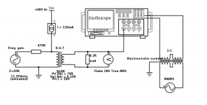
This are the conditions under which the measurements are done: The testing jig has an included current source at 120mA . The driving impedance is 520R.
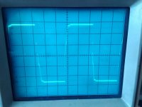
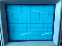
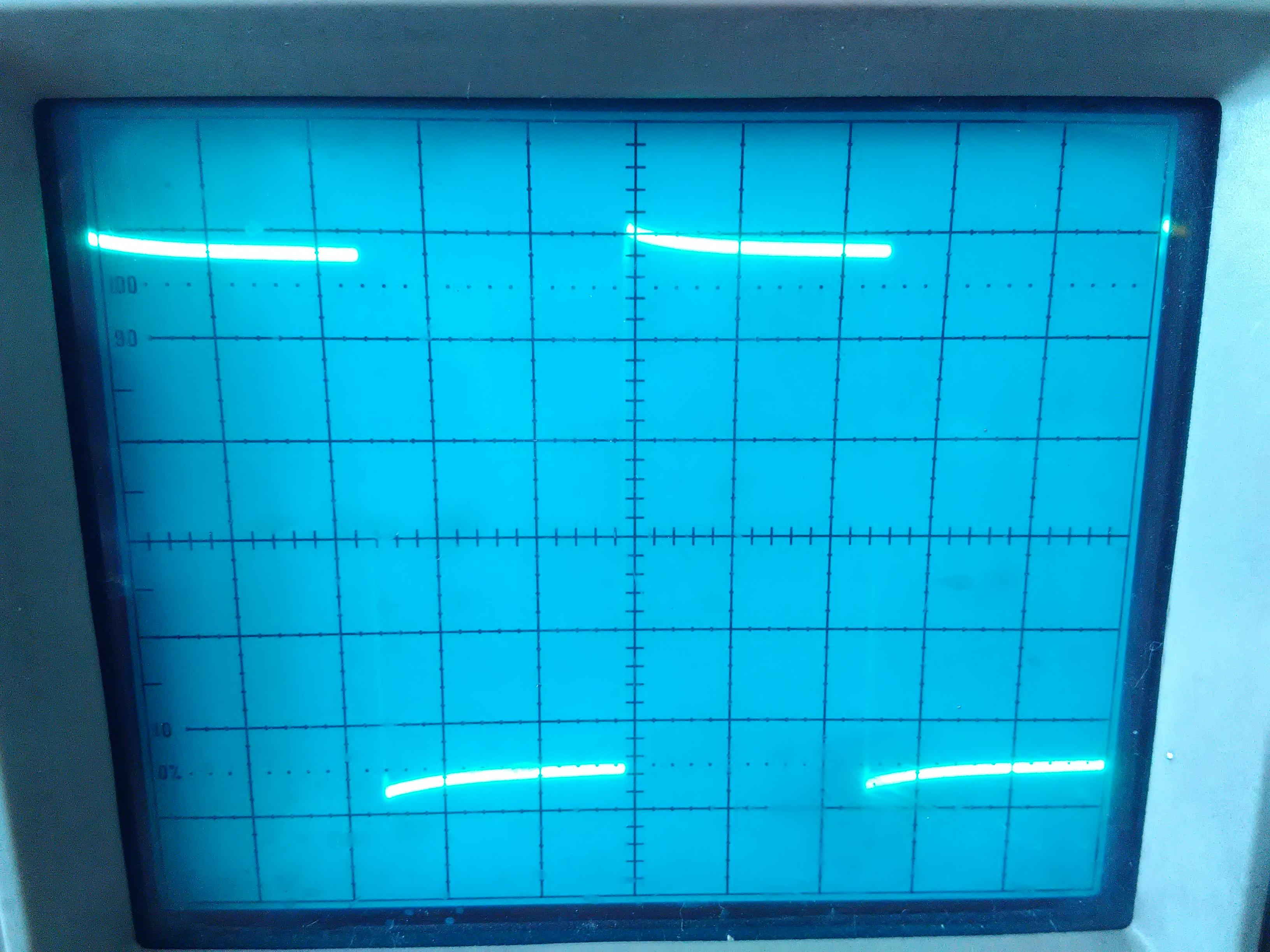
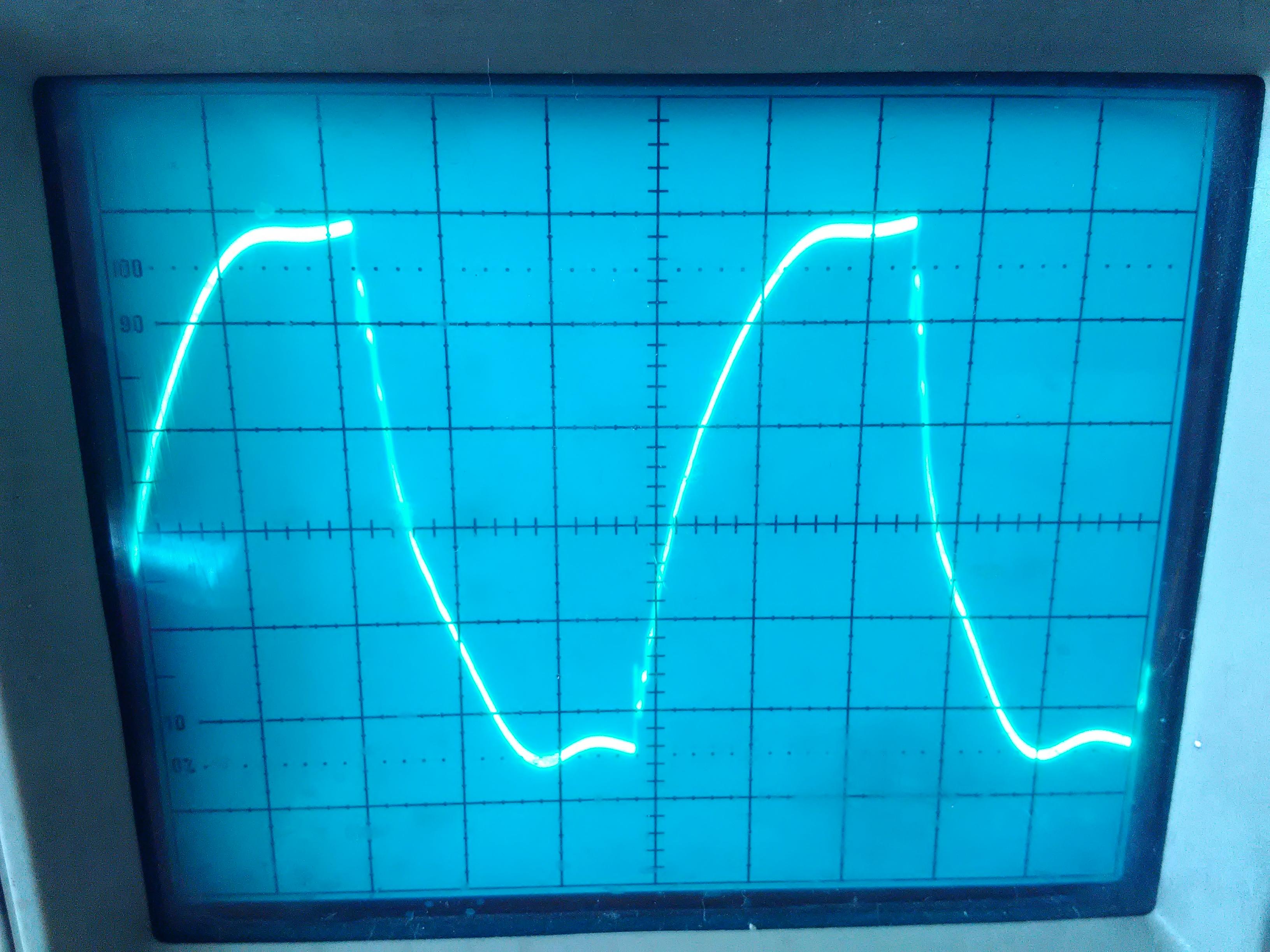
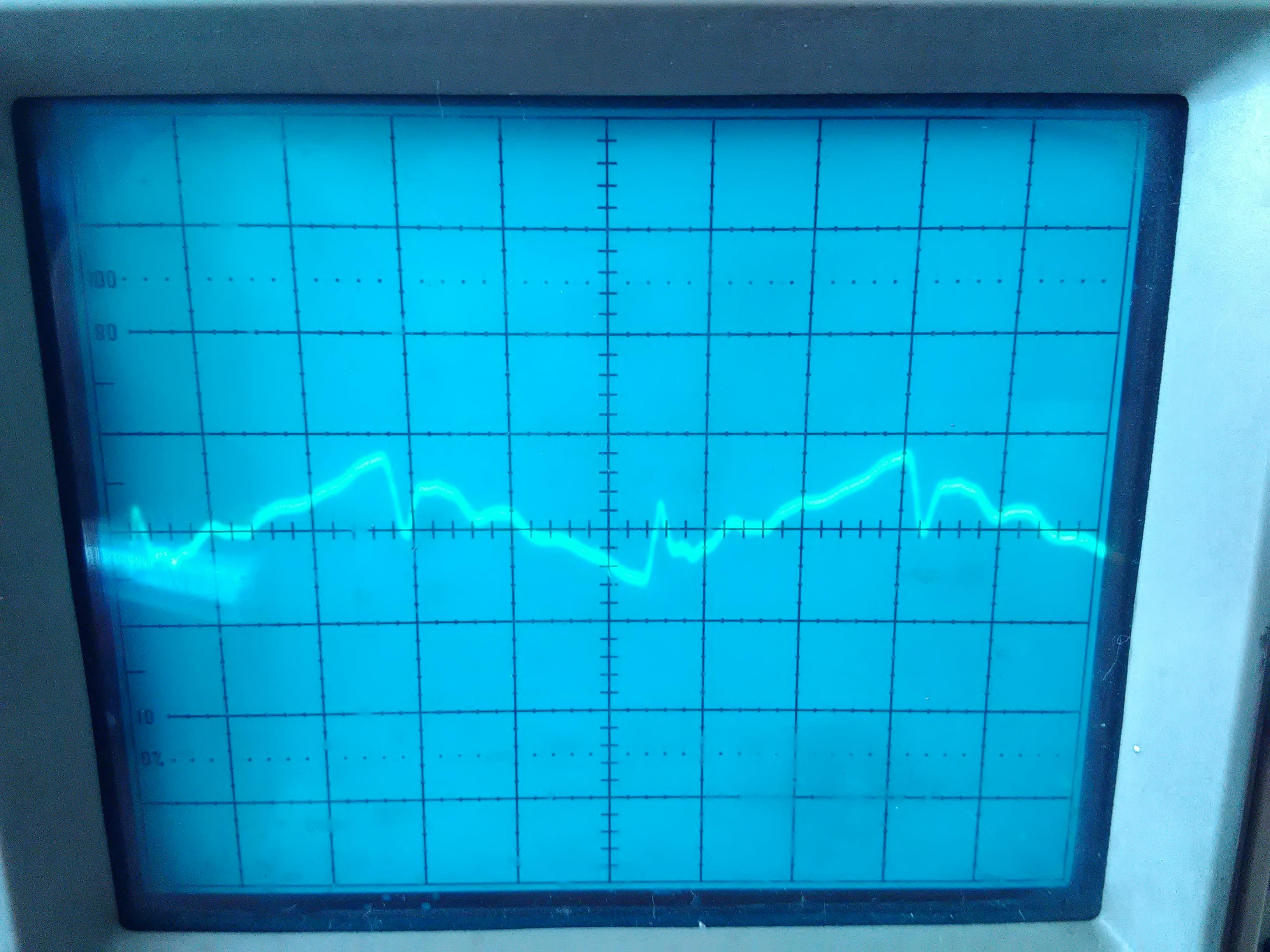
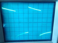
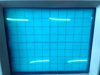
Oscillograms of square waves:
First: 100Hz
Second: 1kHz
Third: 10kHz
Forth: 100kHz
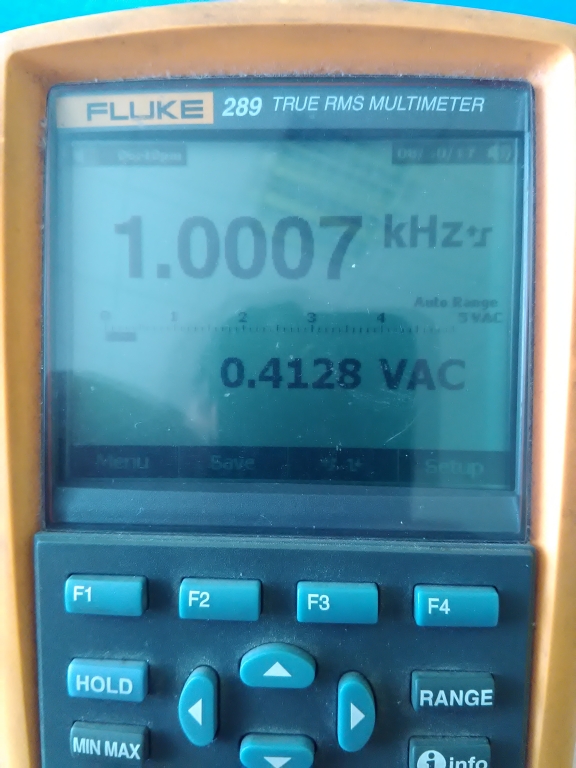
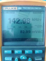
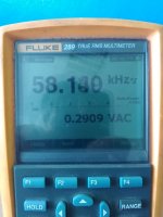
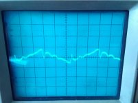
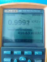
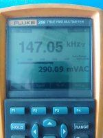
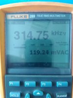
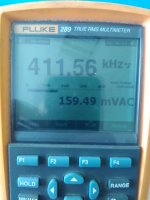
Measured voltage amplitude across the secondary in the following order:
First: 1kHz reference value
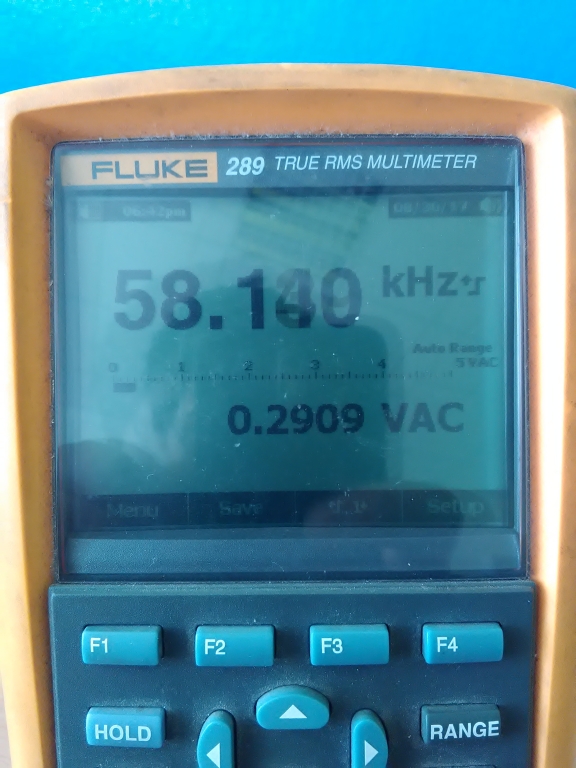
Second: -3dB point in the HF region
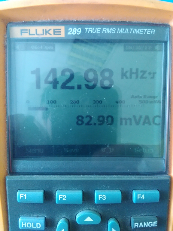
Third: First resonance
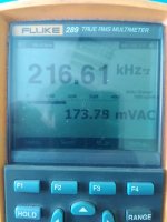
Fourth: Second resonance

Following up -> -> Measurements with a floating secondary.
The machine was free to use for a few days and I managed to finish my transformer. In the same day, I only managed to do simple measurements, such as HF response, HF oscillograms, FR response at a low amplitude under load.
As promised, I will also perform THD tests under 200V RMS at the frequencies of 30Hz, 1kHz and 20kHz, but it will have to wait a bit too. I'm busy with work and I also have to build the measurement jig too.
The transformer's simple description is the following: Z ratio = 3k/8R
Pri turns = 2720
Sec turns = 140
Rdc pri = 70R
Rdc sec = 0.15R
L pri = 18H
Ia = 120mA
Core = 10.4cm2 GOSS
This are the conditions under which the measurements are done: The testing jig has an included current source at 120mA . The driving impedance is 520R.
Oscillograms of square waves:
First: 100Hz
Second: 1kHz
Third: 10kHz
Forth: 100kHz
Measured voltage amplitude across the secondary in the following order:
First: 1kHz reference value
Second: -3dB point in the HF region
Third: First resonance
Fourth: Second resonance
Following up -> -> Measurements with a floating secondary.
Attachments
-
 IMG_20170830_174420.jpg368.7 KB · Views: 443
 -
 Transformer-measurement-grounded-sec.png27.5 KB · Views: 442
 -
 Second resonance.jpg327.4 KB · Views: 421
 -
 First resonance.jpg328.9 KB · Views: 415
 -
 -3dB HF.jpg284.2 KB · Views: 412
 -
 1kHz.jpg281.1 KB · Views: 416
 -
 100kHz oscillogram.jpg432.5 KB · Views: 426
 -
 10kHz oscillogram.jpg409.5 KB · Views: 425
 -
 1kHz oscillogram.jpg404 KB · Views: 417
 -
 100Hz oscillogram.jpg434.4 KB · Views: 421
Last edited:
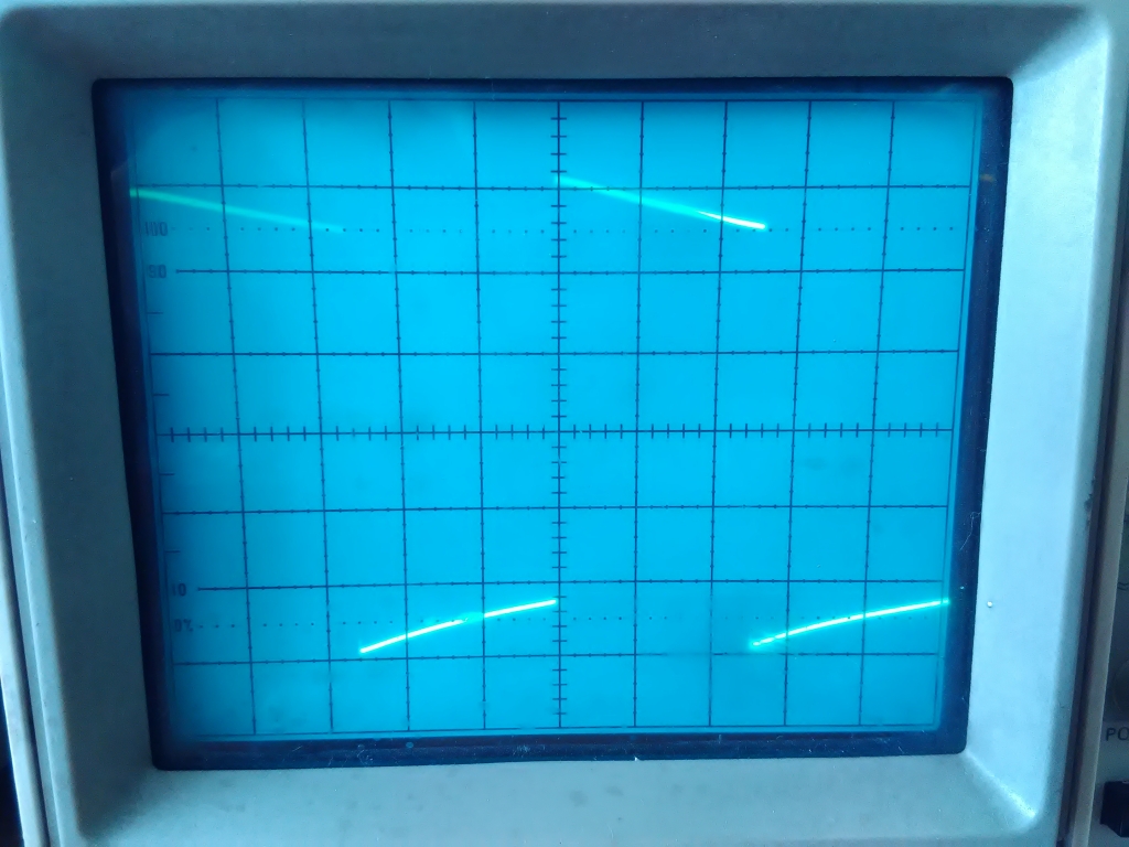
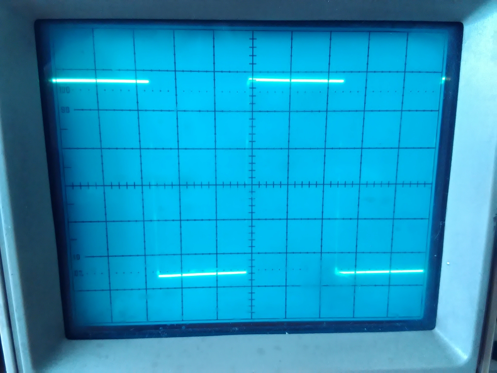
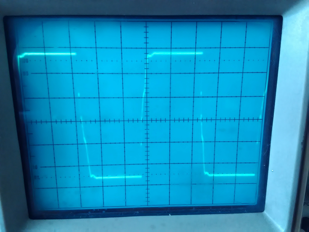
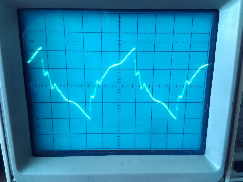
This time, the same measurements are done with the secondary floating. This is done by powering the oscilloscope through a 1:1 isolation transformer with an earthed electrostatic screen.

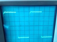
Oscillograms of square waves:
First: 100Hz
Second: 1kHz
Third: 10kHz
Fourth: 100kHz
Fifth: 1MHz


Measured voltage amplitude across the secondary in the following order:
First: 1kHz reference value
Second: -3dB point in the HF region
Third: First resonance
Fourth: Second resonance
Oscillograms of square waves:
First: 100Hz
Second: 1kHz
Third: 10kHz
Fourth: 100kHz
Fifth: 1MHz
Measured voltage amplitude across the secondary in the following order:
First: 1kHz reference value
Second: -3dB point in the HF region
Third: First resonance
Fourth: Second resonance
Attachments
-
 Transformer-measurement-floating-sec.png24.6 KB · Views: 445
 -
 100Hz oscillogram.jpg654.9 KB · Views: 429
 -
 1kHz oscillogram.jpg636 KB · Views: 413
 -
 1MHz oscillogram.jpg625 KB · Views: 411
 -
 100kHz oscillogram.jpg659.8 KB · Views: 425
 -
 10kHz oscillogram.jpg711.5 KB · Views: 418
 -
 1kHz.jpg507.9 KB · Views: 195
 -
 -3dB.jpg485.7 KB · Views: 194
 -
 First resonance.jpg625.8 KB · Views: 190
 -
 Second resonance.jpg605.2 KB · Views: 191
- Status
- This old topic is closed. If you want to reopen this topic, contact a moderator using the "Report Post" button.
- Home
- Amplifiers
- Tubes / Valves
- Yet More Discussion on Winding Output Transformers