I have done the schematic.
http://i51.tinypic.com/qq6fxe.jpg
Hi
Looks ok , remember PIN12 is for power on relay if you use this relay !!!
ATMega8535
For anyone interested for using ATMega8535 (DIP Package in my case) R2R/Shunt Volume controller with RC5 learn and edit text input.
http://www.diyaudio.com/forums/anal...trolers-source-selections-12.html#post2110073
http://www.diyaudio.com/forums/anal...trolers-source-selections-19.html#post2186453
This is the firmware, thanks to Danzup and farmtech
Didiet
Attachments
PGA2310 Gain bytes transmission sequence?
Hi to all
I am building a similar PGA2310 control like this of danzup, simply i use as host controller a PIC16F887 (i have only PIC programmers). From the timing figures of PGA2310 i can suppose that, the transmission sequence of Gain bytes from the host controller to the PGA2310 SDI is:
L0-L1-L2...-L7-R0-R1-R2...-R7 or Left channel bit0 first - Right channel bit7 last.
Is this sequence correct? Or is the inverse sequence correct?
Thanks for any information
Fotios
Lost reply
That was very funny
I received a reply from ------- (he knows, just from respect to him i don't refer his name) in my mail-box and from hurry i deleted the message without read it, because was from diyAudio. When i got into thread the reply was deleted! So, i pulled up the mail from the server of my ISP.
BTW, thanks ------- for the reply, you are very kind. Thanks for your suggestions, but i have proceed enough in my program that is some different from yours, because i use Latching relays and rotary encoder. This moment i am in the process to program the Balance control for PGA2310 and it remains to paste the remote control receiver software. I have all parts needed and i make PCBs at home.
Just i asked the receive sequence of Gain bytes from PGA2310 SDI to be sure. When my project completed, i can share it with you, no problem.
Thanks
Fotios
Fotios when i was writing the firmware i was reading the data sheet and implementing the protocol from there .
If you read my firmware you will understand .
If you need more help just say .
(Sorry I do not have time like those days , even on diyaudio I enter once a week now .)
If you read my firmware you will understand .
If you need more help just say .
(Sorry I do not have time like those days , even on diyaudio I enter once a week now .)
i would like to make a volume bar graph on my LCD for my system. i had try to do it but when i push the button for the volume up the bar goes at the end with every push on the button.
Here is the code that i use for the volume up :
If Command = 16 Then
If Volume < 15 Then
Cls
Locate 1 , 2
Lcd " Volume: "
Incr Volume
Locate 1 , 11
Lcd Volume
Locate 2 , 2
For position = 1 To 16
For Bar = 2 To 6
Locate 2 , Position
Lcd Chr(bar)
'Waitms 700
Next
Next
Else
Locate 1 , 11
Lcd "MAX!"
End If
End If
Any ideas? (Im using bascom)
Hi all,
i have some problems with this attanuator (Farmtech software, R2R no VU). I have try software for ATmega16 and 32. The problems is when i use encoder. When I turn it quickly ATmega go to sleep or reset. Every time. I didnt try remote.
I use this encoder: http://home.comet.bg/datasheets/Buttons/ED1112S-ok.pdf
Is this problem with this encoder, should i have to chnage it for another, or i do something wrong?
This is PCB:
Thanks in advance.
Boban
i have some problems with this attanuator (Farmtech software, R2R no VU). I have try software for ATmega16 and 32. The problems is when i use encoder. When I turn it quickly ATmega go to sleep or reset. Every time. I didnt try remote.
I use this encoder: http://home.comet.bg/datasheets/Buttons/ED1112S-ok.pdf
Is this problem with this encoder, should i have to chnage it for another, or i do something wrong?
This is PCB:
An externally hosted image should be here but it was not working when we last tested it.
Thanks in advance.
Boban
Last edited:
Encoders
Rotary encoders with detents have 2 different patterns (from those i have tried so far).
1) ALPS - BOURNS: In each detent position, both A and B outputs are 0V (LOW state). A small debounce space beside each detent position is also provided.
2) Panasonic: In each detent position, output A is either LOW or HI, while output B is not specified.
Your encoder has same pattern like Panasonic.
You must use a same pattern Encoder like this of Farmtech original project, unless you should change the program code.
Last edited:
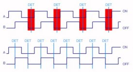
Encoder Patterns
In the attached pic you can see for what i am talking. Both patterns are obtained with COM pin of encoder connected at +V.
The upper pattern is that produced from ALPS or BOURNS encoders. The blue vertical lines are detent positions. The red shaded area is the debounce time offered.
The lower pattern is that produced from Panasonic (and your own encoder). I hope you can understand why B output of encoder is not defined. It can be either HI(On) or LOW(Off) because its transition edge is located exactly at the detent line (position).
On my own view, ALPS pattern is most easily implemented in program code because its A & B outputs have fixed LOW(Off) state at detent positions.
Attachments
Thanks for your reply. I will try to find ED16112O or ED16112M.
Lot of ALPS and BOURNS at Farnell.UK. ALPS from 1,65 - 6GBP and BOURNS from 1,5GBP.
Here on e-bay: Alps Rotary Encoder with 30 Detents | eBay
This one is also nice : BOURNS|PEC11-4220F-S0024|INCREMENTAL ENCODER | Farnell United Kingdom
This one is also nice : BOURNS|PEC11-4220F-S0024|INCREMENTAL ENCODER | Farnell United Kingdom
Yes, is perfect and has built in momentary switch (can be used e.g. for MUTE function, or MENU selection etc). The only problem with Farnell (i am customer of it) is that charges an arm and a leg
to ship orders in our countries.Good night
Fotis
Today i was try this encoder : BOURNS|PEC11-4020F-S0024|Incremental Encoder | Farnell United Kingdom , found it in local store, and i have the same problems described in post 551. This encoder is without detents.
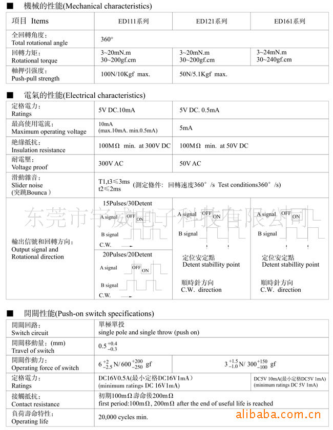
Do I have to use strictly ED16112O or ED16112M for this project? On the picture is datasheet for those encoders:
Boban
Do I have to use strictly ED16112O or ED16112M for this project? On the picture is datasheet for those encoders:
Boban
Last edited:
Hi Boban
Pinout of this encoder is:
Left pin = A switch
Center pin - Common terminal
Right pin = B switch
Try to connect A (Left pin) and B (Right pin) in inverse way on PCB, A in the place of B and B in the place of A.
Can you post the schematic please?
Fotis
Pinout of this encoder is:
Left pin = A switch
Center pin - Common terminal
Right pin = B switch
Try to connect A (Left pin) and B (Right pin) in inverse way on PCB, A in the place of B and B in the place of A.
Can you post the schematic please?
Fotis
Last edited:
- Home
- Source & Line
- Analog Line Level
- Yet another Volume controlers and source selections