Here is my 2 cents worth
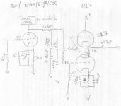
I experimented with this design in which I subbed the D3a/E180f/E280f/C3G for the first stage. I tried the Ixys 10m45 current regulator but eventually settled on a 33k anode resistor feeding the c3G.The cathode resistor for the C3g was 330R and I used a 1k grid reistor instead of the 100 as depicted.
Like you I had a stock of 6SL7's so after experimentation I settled on an srpp design which for me sounded best.
I built a lot of phono stages including ccs/mu stage and Kimmel mu stage before I settled on this schematic.
All the grounds for this stage went to the ground of the input socket ( i have a bus bar arrangement there) which then went to the central star ground point.
Regards
Nick
Attachments
Over a month later, and I finally have something working. Here's where it is schematic wise. I'll post some pics once I slap a chunk of wood to the front.
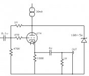
I ended up using Jim Hagerman's riaa calculator with split stages. The first go with the combined stage just didn't sound right. I also used two stages of 6GK5 for gain as the 6gk5 to 6T4, as predicted by others, just didn't cut it. I also blew out the mosfets while tinkering, and of course had not bought more. So, the mosfet followers got replaces with a more wholesome cathode follower, and since the 6T4's used the spots drilled for the gas regulators, I resorted to a zener based shunt reg -- at 100V as that is what was in the drawer.
I think the next step is to drill some more holes to put the gas tubes back in as they are more glowey. Maybe a CCS in the cathode of the follower, too.
I think it sounds good -- my table and cartridge are really limiting factors here, so I'll need to find someone with a nicer turn table to really listen to it. But, I have at least had the opportunity to reacquaint myself with some of the more classic recordings in my collection.
Attachments

SY said:The output CF is very problematic; you've got a super-low load and very little swing capability. Try biasing up the grid 40 or 50V, then resize the cathode resistor accordingly.
Good catch, I think. On hot recordings, there is a little crackling that I had not tracked down, so I think you are correct about the source.
Is the attached what you mean? This should bias the grid to ~32V, and I think run just under 20mA though the tube bringing the cathode to ~34 or 35V point. I probably need to check my math again, but I think this is close.
revintage said:Remove the gridleak from the 6T4 and the coupling cap from the presceding stage. The CF will then be biased from the 6GK5 and you could use the CCS as a current sink instead of the super-low value cathode resistor.
It's a good idea, but the plate of the 6GK5 is at close to 120V and this is too close to B+ for this to work here. Also, the PS is pretty noisy so it needs the shunt reg, or something, to keep it quiet. But, in the original version when I had a 6T4 as the second tube (w/ about 70V on the plate), this is essentially what I was doing which was why I wanted that tube there in the first place.
Attachments
It's a good idea, but the plate of the 6GK5 is at close to 120V
The 6GK5s with its somewhat odd workingpoint will probably have as much problems as the CF
") .
. This little spreadsheet could maybe be of some help:
www.revintage.se/triodecalc.xls
revintage said:The 6GK5s with its somewhat odd workingpoint will probably have as much problems as the CF
What's odd about the operating point of the 6GK5?
Attachments
SY said:That's better, but 1800 ohms is still a pretty low load. It'll probably work, but a CCS there would drop the distortion a notch or three.
It made a world of improvement. I ordered some transistors to add the cathode CCS.
SY said:You might also have some overload issues in the first stage, especially during mistracking events.
It seems OK, but looking at the filter calculations, I think that first Rk is supposed to be more like 60R anyhow which should take care of the possibility.
Butte, MT?
What's odd about the operating point of the 6GK5?
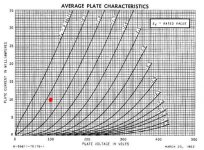
Another odd thing is that it does not show the working point of your amp that you said where 120V, 12mA!
100V, 10mA is good but does it take CCS loss and load in consideration?
So assuming the CCS isn´t lossless and that you have a frequency depending load I still consider your initial figures odd.
When adding the current sink as I suggested, maybe you could add a low-DCR choke and a cap on top for filtering to get less voltage loss. But your CCSd shunt will of course work.
revintage said:Another odd thing is that it does not show the working point of your amp that you said where 120V, 12mA!
100V, 10mA is good but does it take CCS loss and load in consideration?
So assuming the CCS isn´t lossless and that you have a frequency depending load I still consider your initial figures odd.
Not sure I follow you exactly. B+ is about 155V or so. The CCS sets a current and the bias resistor sets a plate voltage. The CCS drops the volts it needs to. The curves for the second tube suggest it should be at around 100V. In actuality, it is closer to 120V. But, this still gives a 35V drop across the CCS which is plenty.
One point of the CCS is that the plate voltage, and in fact B+, can be largely ignored other than being sure it is reasonable. B+ of up to 300V would be fine here -- 300V is the limit of the transistors I used. (The other advantages are the high load for the tube, the drastic reduction in ripple which makes the raw power supply almost incidental, the easy control over the circuit, the reduced B+ requirements, and that the PS caps are isolated form the signal current path.)
revintage said:When adding the current sink as I suggested, maybe you could add a low-DCR choke and a cap on top for filtering to get less voltage loss. But your CCSd shunt will of course work.
I think the CCS works better here. The PS is really noisy so the regulator does a world of good.
Finally got this in a usable way. I replaced that final cathode resistor with a CCS. Not sure I am enamored with the change, but I'll listen for a while. Overall, seems to work pretty well. Most of the parts in the build were scavenged, or left overs from other projects -- I bought the 6GK5's (at Eli's suggestion) and the filter caps.
The PS is a generic CLC. It uses a toroid in Poinz's clever configuration for HT. The heater supply is a basic LM317 (LT1084 actually) with a switch to swap between 6.3 and 12.6V operation. It gets used as a raw supply for various lowish voltage projects.
A final schematic and a few pictures:
The PS is a generic CLC. It uses a toroid in Poinz's clever configuration for HT. The heater supply is a basic LM317 (LT1084 actually) with a switch to swap between 6.3 and 12.6V operation. It gets used as a raw supply for various lowish voltage projects.
A final schematic and a few pictures:
An externally hosted image should be here but it was not working when we last tested it.
An externally hosted image should be here but it was not working when we last tested it.
An externally hosted image should be here but it was not working when we last tested it.
An externally hosted image should be here but it was not working when we last tested it.
An externally hosted image should be here but it was not working when we last tested it.
- Status
- This old topic is closed. If you want to reopen this topic, contact a moderator using the "Report Post" button.
- Home
- Amplifiers
- Tubes / Valves
- Yet Another Phono Stage Suggestions Thread