Although this preamp is 4-channel & seems bulky & complex, it's indeed a "simpler solution" to my "existing system" ")
One can never go back when he/she has tried active xover in the multi-way speaker system, especially with a low xover point like mine.
I adore the simplest full range concept too & use a pair of Jordan Watt in the bedroom. However in the main system, I need bigger SPL & scale from time to time
About the LL1630, I checked the datasheet & found it can only stand 9mA DC max & suggested 5mA when the primary coils are in series. Running them in parellel would double it, but still in a lowish 10mA range.
Jaap, how do you set your operation point & the "coil configuration" ?
LL1630
I have some LL1630's with a gap for 10 mA. With parallel primaries you can put 20 mA through them. I believe it is better to not exceed 20 mA with the 5842 for the most relaxed sound.
I certainly believe that bi-amping is the better way. Thanks for the reminder, this is one of my future projects. I will also make a model with 4 channels in the future.
I followed the schematic of Ciuffoli (headwize) with a tube rectifier (5Y3) and 3 chokes for 2 channels. I used a 100K dact attunuator. LL1630 a la ciuffoli.
As I said, I am very pleased with the result.
JH
... I guess connecting the GND of balance input to the secondary's ground might resolve this full output buzz..... [
Yes it does!
I tried this via a little 24uH toroid choke. It cured the high output buzz completely
And I can't hear any sonic differeces, which should be a good thing.operating point 5842
datasheets tell you nothing about good sound
http://db.audioasylum.com/cgi/m.mpl?forum=set&n=24373&highlight=5842&r=&session=
I know that Thorsten has an opinion about this subject.
You can also do a search on set or tube diy asylum
datasheets tell you nothing about good sound
http://db.audioasylum.com/cgi/m.mpl?forum=set&n=24373&highlight=5842&r=&session=
I know that Thorsten has an opinion about this subject.
You can also do a search on set or tube diy asylum
Maybe it's because our tastes are so different. Do you mind making further desciptions for "relaxed sound" ?
My understanding on the operation point is "make it as linear as possible".
I've never made any curve tracing myself, so maybe I'm not in the right position to say what exatly the tubes work. However, on paper (no matter it's a "datasheet" or someone's real test results), EVERY plate I/V curve I've seen is bending on the bottom, i.e., low current region. Doesn't that mean "non-linear" ? If so, I want to avoid that as far as possible.
On datasheets, the "curves" might probably be much more optimisic than the real life. Even we take it as it is, it's still curvy/non-linear in the low current operations. And, I've seen some real test cures show some really big bad bendings on the low current region.
If I'm lucky enough to get tubes somewhere in between, I'd still better run them warmer to avoid the curvy part.
As to their sounds, I prefer the one with big current after I tried them at quite some different operations. No matter on FETs, triodes, pentodes, I prefer big current on them all
operating point 5842-ping Thorsten
If you are certain about what you want and if you have it then you are a lucky guy
I refer to a discussion some time ago on a forum I don't remember and I cannot find anymore. The discussion on the same subject ended in better results soundwise for lower current on the 5842. This confirms my own experience using my ears and not my eyes. I remember that Thorsten or Kuey ....... had a very clear opinion based on empirical evidence on this. Perhaps he can repeat that
Updates
It's almost a year.
Recently I've been thinking rebuilding some parts of this pre amp. It's because: 1. I can do it better (I should). 2. I met some tubes which are noisy, I'm thinking if it's because the bad arrangement of grid stopper.
So, here it is:
Old & new:
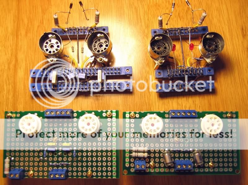
Yes, the new ones are built on PC boards, but it's some kind of bread board, only proivde supporting. All circuits are still point to point hard wired.
Grid stoppers & "buried" cathode LED:
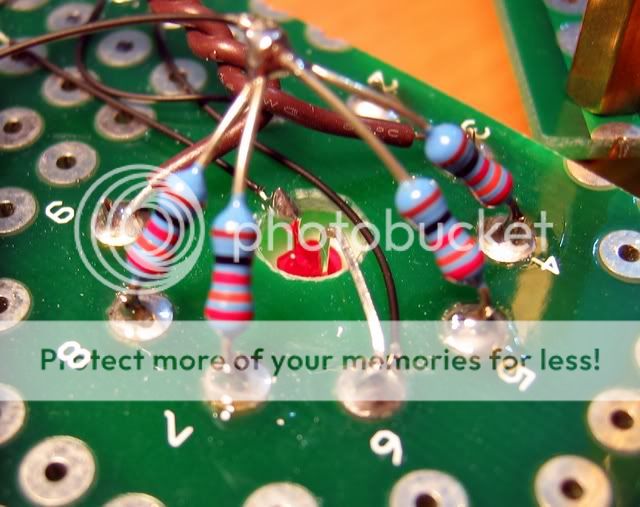
Hehe, I stole someone else's idea to stuff the LED into the center hole of tube socket.
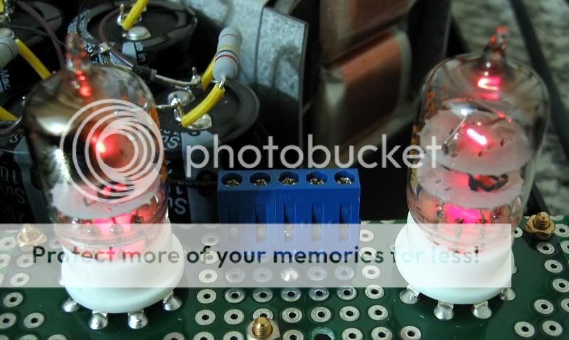
LEDs are lighting up the bottom of tubes:
Putting them all together:
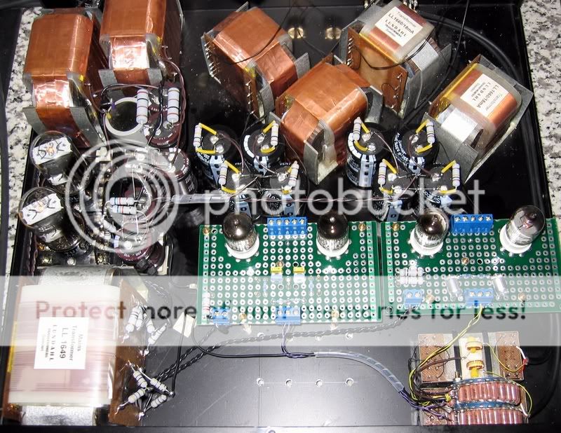
Circuit-wise, I changed the rectifier to 6W4GT, and added 330uF ultrapath cap for each tube. The lowpass filter is changed to 1st order. (Maybe I'll keep playing with this later... )
The OPT is configured as 6k:300 by a 300R on the secondary. The operation point is about 165V on anode, 2.2V on cathode, 16mA.
One of the major reason I make this mod is to see if the "correct" grid stopper would eliminate the tube's noise, but unforturnately it dosen't.
It's almost a year.
Recently I've been thinking rebuilding some parts of this pre amp. It's because: 1. I can do it better (I should). 2. I met some tubes which are noisy, I'm thinking if it's because the bad arrangement of grid stopper.
So, here it is:
Old & new:
Yes, the new ones are built on PC boards, but it's some kind of bread board, only proivde supporting. All circuits are still point to point hard wired.
Grid stoppers & "buried" cathode LED:
Hehe, I stole someone else's idea to stuff the LED into the center hole of tube socket.
LEDs are lighting up the bottom of tubes:
Putting them all together:
Circuit-wise, I changed the rectifier to 6W4GT, and added 330uF ultrapath cap for each tube. The lowpass filter is changed to 1st order. (Maybe I'll keep playing with this later... )
The OPT is configured as 6k:300 by a 300R on the secondary. The operation point is about 165V on anode, 2.2V on cathode, 16mA.
One of the major reason I make this mod is to see if the "correct" grid stopper would eliminate the tube's noise, but unforturnately it dosen't.
Oh, I forgot to mention a strange thing.
The sockets on the board were so damn tight, plugging in the tubes for the first time was very difficult....
When the first time I turned it on, microphonics was very bad. When turning down, the last click of the stepped antenuator made a very loud bang through the speakers. Other vibrations like tapping on the chassis made similar effects.
So bad, but the same set of tubes were working good on the old sockets without such trouble, why not on these new ones? Is it because the boards are rigidly mounted on the chassis while the old ones are conventional type which allow some movement for shock buffer?
I don't know.
Later I pulled all tubes off & got another 9pin tube with longer bottle & sharper pins to be a tool to loose up the sockets a bit.
It worked. Still very tight but reasonable. Good thing is, plugged all tubes back in, the microphonics was gone.
But, why? Was the first attempt damage the tubes? When I plugged them hard into the tight sockets, any chance to make the pins loosen on glass or affect the interal parts? However, no matter what, it seemed cured on the second attempt. Strange.
---------------------
BTW, it sounds a little tighter & agile than before. I'm not sure it's because the change on LP filter or the ultrapath caps...
I've been playing around the heater elevation these days for the noisy Amperex gold pin.
Originally the AC heater supply was center tapped by resistors & set on 23V above ground.
From the very long 12B4 line stage thread, I read "too high of this voltage might cause problem, too".
By that suggestion, I modified this portion with a muli-turn pot to get adjustable voltage divider.
Set it on 10V, the noise came down, but still there. Turned it down to 5V, the noise was completely gone. So it was indeed the heater-cathode leak!
In 2 or 3 days of using, I've only heard that scratching noise for once or twice, much better than the "continuous" scratch before.
But I'm still can't figure out why it is so. Set the heater more positive should cut the leak more efficient, why opposite in reality? Must be something wrong here.
In Morgan Jones's book, it said the bad heater-cathode insulation can be "cured" by raising the heater supply voltage by a certain propotion, then running it with over anode current, to burn the possible debris.
Kind of scary to me. Anyone tried it? How did it work out?
Originally the AC heater supply was center tapped by resistors & set on 23V above ground.
From the very long 12B4 line stage thread, I read "too high of this voltage might cause problem, too".
By that suggestion, I modified this portion with a muli-turn pot to get adjustable voltage divider.
Set it on 10V, the noise came down, but still there. Turned it down to 5V, the noise was completely gone.
So it was indeed the heater-cathode leak! In 2 or 3 days of using, I've only heard that scratching noise for once or twice, much better than the "continuous" scratch before.
But I'm still can't figure out why it is so. Set the heater more positive should cut the leak more efficient, why opposite in reality? Must be something wrong here.
In Morgan Jones's book, it said the bad heater-cathode insulation can be "cured" by raising the heater supply voltage by a certain propotion, then running it with over anode current, to burn the possible debris.
Kind of scary to me. Anyone tried it? How did it work out?
- Status
- This old topic is closed. If you want to reopen this topic, contact a moderator using the "Report Post" button.
- Home
- Amplifiers
- Tubes / Valves
- Yet Another "EURIDICE" Pre Amp, 4CH This Time