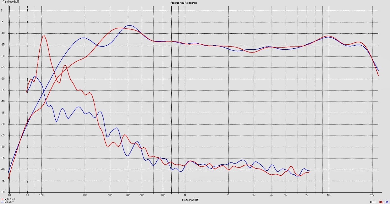
So this is how 2 AMTs in a 70 cm waveguide (see post #276 for picture) measures at the listening position:
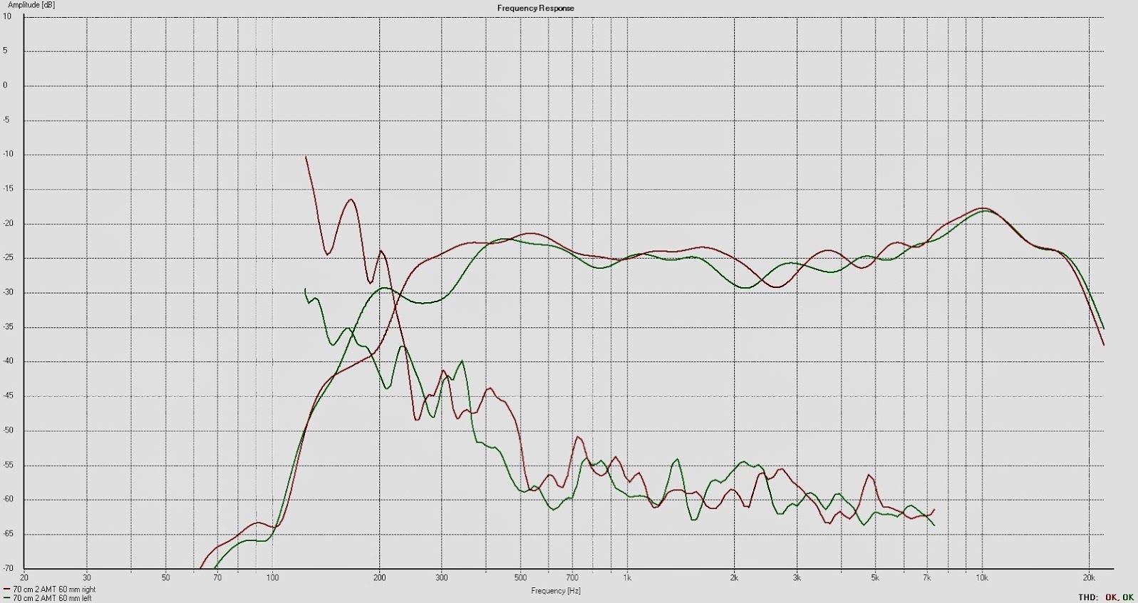
Still have to work on the lf to get the distortion down a bit, right speaker is a little bit high at 400 Hz.
Again, the 5 dB top around 10 kHz is equalized. XO -24 dB/octave to the TD15Hs at 400 Hz.
Still have to work on the lf to get the distortion down a bit, right speaker is a little bit high at 400 Hz.
Again, the 5 dB top around 10 kHz is equalized. XO -24 dB/octave to the TD15Hs at 400 Hz.
Last edited:
While hunting for the distortion source for the lf in the right speaker, I realized that the cutout for the AMTs in the support beam for the TD15Hs is only 65 mm behind the AMT´s rear.
So there´s a potential risk that the reflected back wave will interfer with the front wave with distortion or cancellation around those frequencies (even parts or multipels of 344/0,065).
So adding dampening material between the beam and the rear of AMT resulted in lower distortion and a more even frequency response. In fact, I have now removed the EQ at 10 kHz.
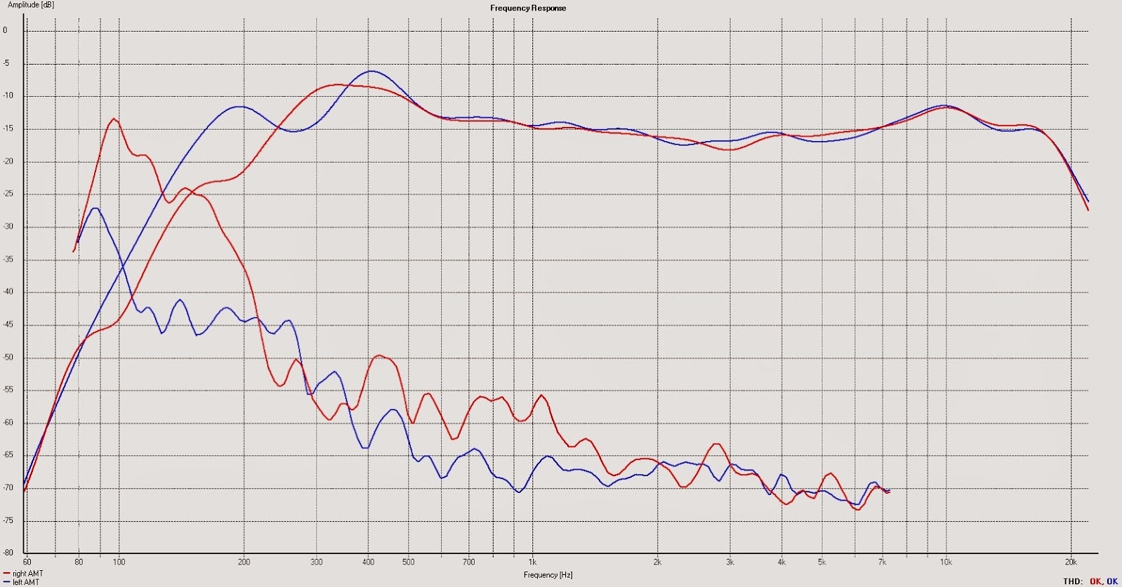
Still some issues below 250 Hz for the right AMT though.
BTW, I measured the room "silent". It seems that there are background noise below 1 kHz as well. Just by turning off the projector made the 225 Hz and the multiples of that go away:
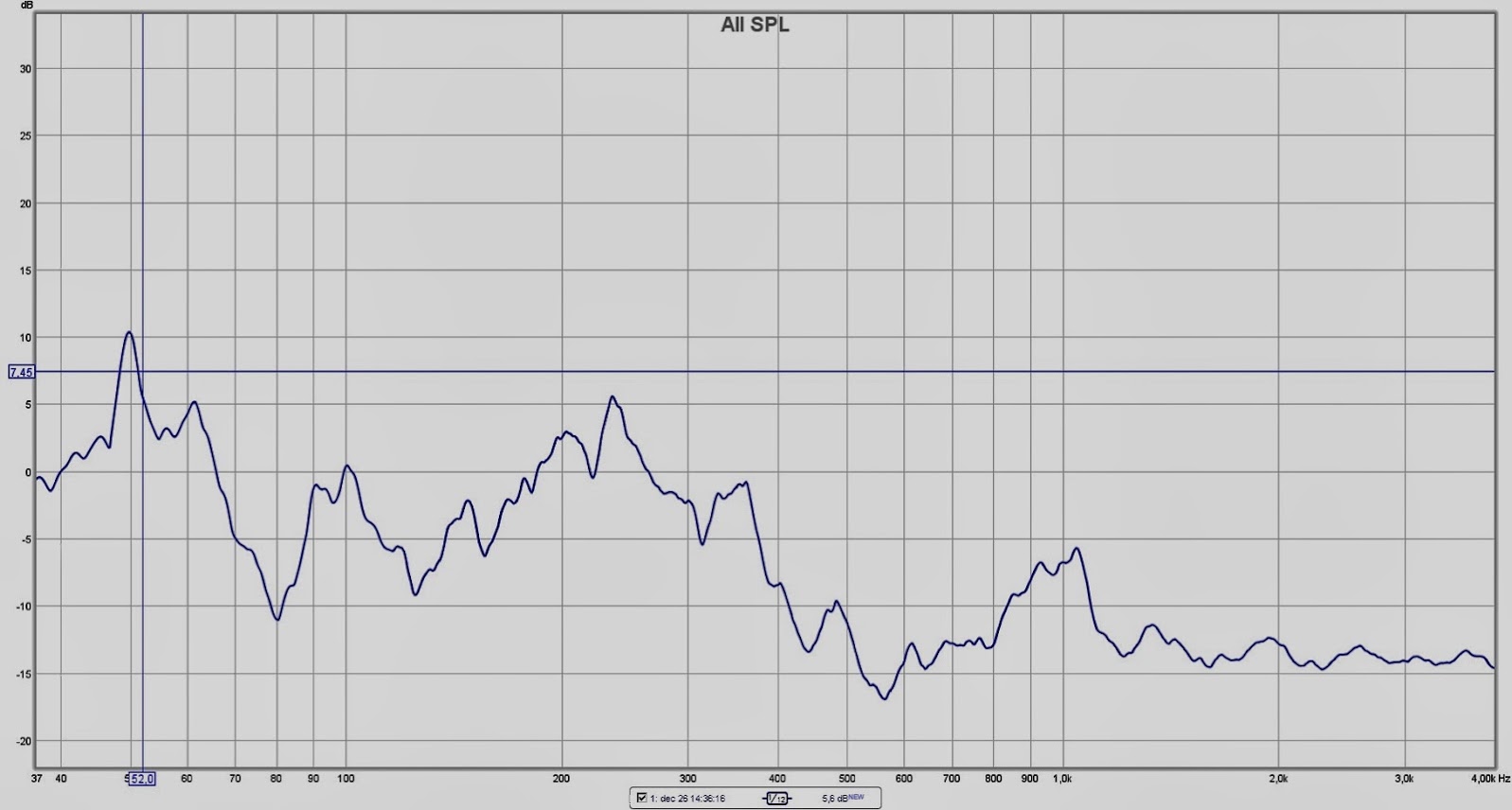
So one has to be careful what one is actually measuring in a home environment.
So there´s a potential risk that the reflected back wave will interfer with the front wave with distortion or cancellation around those frequencies (even parts or multipels of 344/0,065).
So adding dampening material between the beam and the rear of AMT resulted in lower distortion and a more even frequency response. In fact, I have now removed the EQ at 10 kHz.
Still some issues below 250 Hz for the right AMT though.
BTW, I measured the room "silent". It seems that there are background noise below 1 kHz as well. Just by turning off the projector made the 225 Hz and the multiples of that go away:
So one has to be careful what one is actually measuring in a home environment.
As the AMT and waveguides are in the same baffle as the TD15Hs, they have the same angle/toe in.
I use silicone rubber to attach the membranes to two vertical wooden sticks, not the prettiest thing I´ve done but it will do for now:

The whole construction is squeezed in between the magnetes and a couple of EPDM rubber molding:
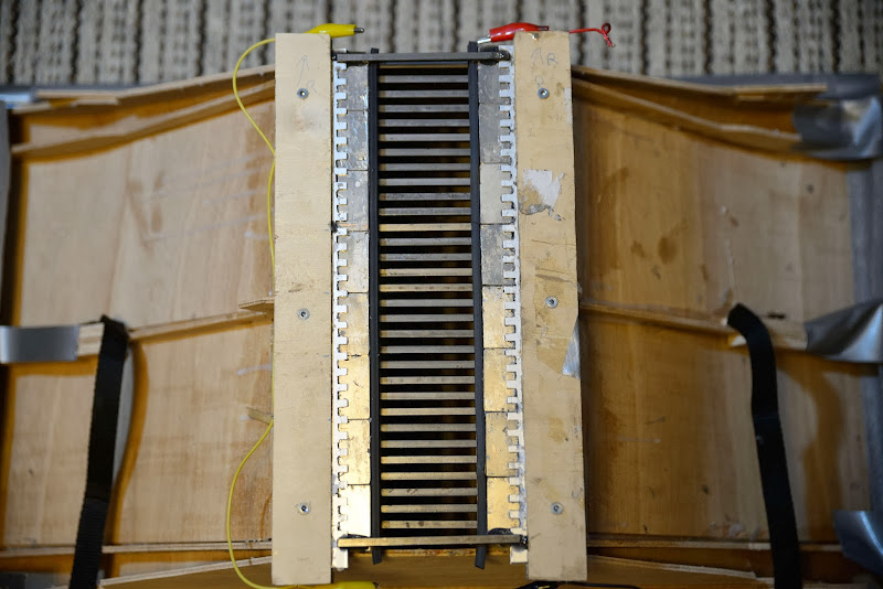
Then the remaining rods are installed. Note that these only are held in place with magnetic force:
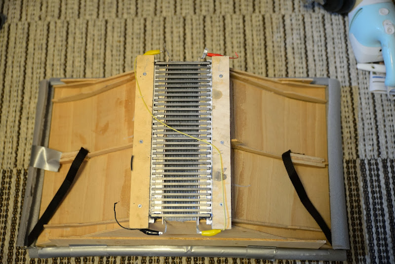
The picture above does not show the molding, and the polarity is wrong.
I will perhaps experiment with your type of frames later on, Bernt.
I don´t know about line arrays though. They might be constructed to measure alright, but from my experience a year ago, they sound - dull.
But perhaps it is different with AMTs. Still got some Neo from my ribbon project so I might do something with them in future as well.
Now I am, hopefully, going to listen to this setup during the remainder of this holiday season.
Season Greetings to you all:


I use silicone rubber to attach the membranes to two vertical wooden sticks, not the prettiest thing I´ve done but it will do for now:
The whole construction is squeezed in between the magnetes and a couple of EPDM rubber molding:
Then the remaining rods are installed. Note that these only are held in place with magnetic force:
The picture above does not show the molding, and the polarity is wrong.
I will perhaps experiment with your type of frames later on, Bernt.
I don´t know about line arrays though. They might be constructed to measure alright, but from my experience a year ago, they sound - dull.
But perhaps it is different with AMTs. Still got some Neo from my ribbon project so I might do something with them in future as well.
Now I am, hopefully, going to listen to this setup during the remainder of this holiday season.
Season Greetings to you all:
Yes, I´m definitily on the right track here.
I have been able to lower the XO to 250 Hz.
I must have better folding precision, lower resistance and better frame, though:
As I have a 6,5/1,5 folding ratio I thought of change the alu/space ratio from 5/3 to 5,5/2,5.
This to get more area that is direct driven but also to get lower resistance.
Today I got a total of 9 ohms so the obvious goal is to get to 8 ohms.
I also plan to make the membrane a little bit higher than what the 74 film allows me to.
So it will be 165 mm high but with the horisontal alu parts folded to get within the 160 mm film.
To fixate the unsupported alu I plan mold the silicone at the ends instead of just applying the silicone.
And last, I will test to have brass instead of wood as sides. This as wood tends to bulge in the middle.
The brass is 4x1,5 mm so it will allow me to center it in the gap.
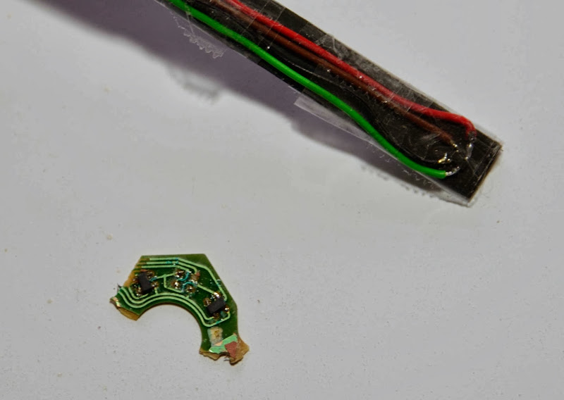
I´ve made a simple Gauss Meter following this instruction.
It actually works, but it is un-linear for any absolute measurements.
But it can for sure be used to investigate if any of the magnetes are mounted incorrect or, as for my motors, how the field varies between the rods in the gap.
I have been able to lower the XO to 250 Hz.
I must have better folding precision, lower resistance and better frame, though:
As I have a 6,5/1,5 folding ratio I thought of change the alu/space ratio from 5/3 to 5,5/2,5.
This to get more area that is direct driven but also to get lower resistance.
Today I got a total of 9 ohms so the obvious goal is to get to 8 ohms.
I also plan to make the membrane a little bit higher than what the 74 film allows me to.
So it will be 165 mm high but with the horisontal alu parts folded to get within the 160 mm film.
To fixate the unsupported alu I plan mold the silicone at the ends instead of just applying the silicone.
And last, I will test to have brass instead of wood as sides. This as wood tends to bulge in the middle.
The brass is 4x1,5 mm so it will allow me to center it in the gap.
I´ve made a simple Gauss Meter following this instruction.
It actually works, but it is un-linear for any absolute measurements.
But it can for sure be used to investigate if any of the magnetes are mounted incorrect or, as for my motors, how the field varies between the rods in the gap.
As the AMT and waveguides are in the same baffle as the TD15Hs, they have the same angle/toe in.
I use silicone rubber to attach the membranes to two vertical wooden sticks, not the prettiest thing I´ve done but it will do for now:
The whole construction is squeezed in between the magnetes and a couple of EPDM rubber molding:
Then the remaining rods are installed. Note that these only are held in place with magnetic force:
The picture above does not show the molding, and the polarity is wrong.
I will perhaps experiment with your type of frames later on, Bernt.
I don´t know about line arrays though. They might be constructed to measure alright, but from my experience a year ago, they sound - dull.
But perhaps it is different with AMTs. Still got some Neo from my ribbon project so I might do something with them in future as well.
Now I am, hopefully, going to listen to this setup during the remainder of this holiday season.
Actually I have been playing with them during all that next year and this holiday season as well. Without changing or modifying anything (did some paint job though).
Have been at two DIY meetings during the year and also have had a dozen of "golden ears" visited at home. All awed by the clarity of the setup.
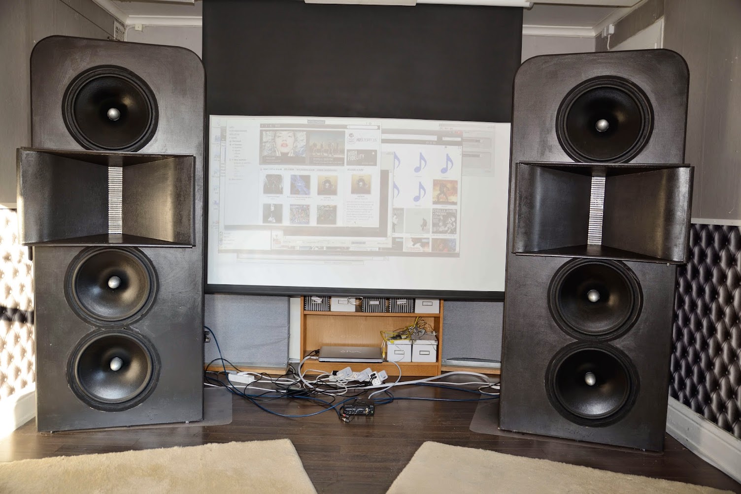
For the better part of the year I've messing around with a planar bass, a project I now have abandoned
 .
.I now realize that my three AE TD15H
 aside never will be beaten.
So it is high time for Mk II of my DIY AMT
 .
.There are many degrees of freedom, but re-use of the wave guide reduces the number a little.
As usual I'll start with some FEMM simulations, here's a teaser:
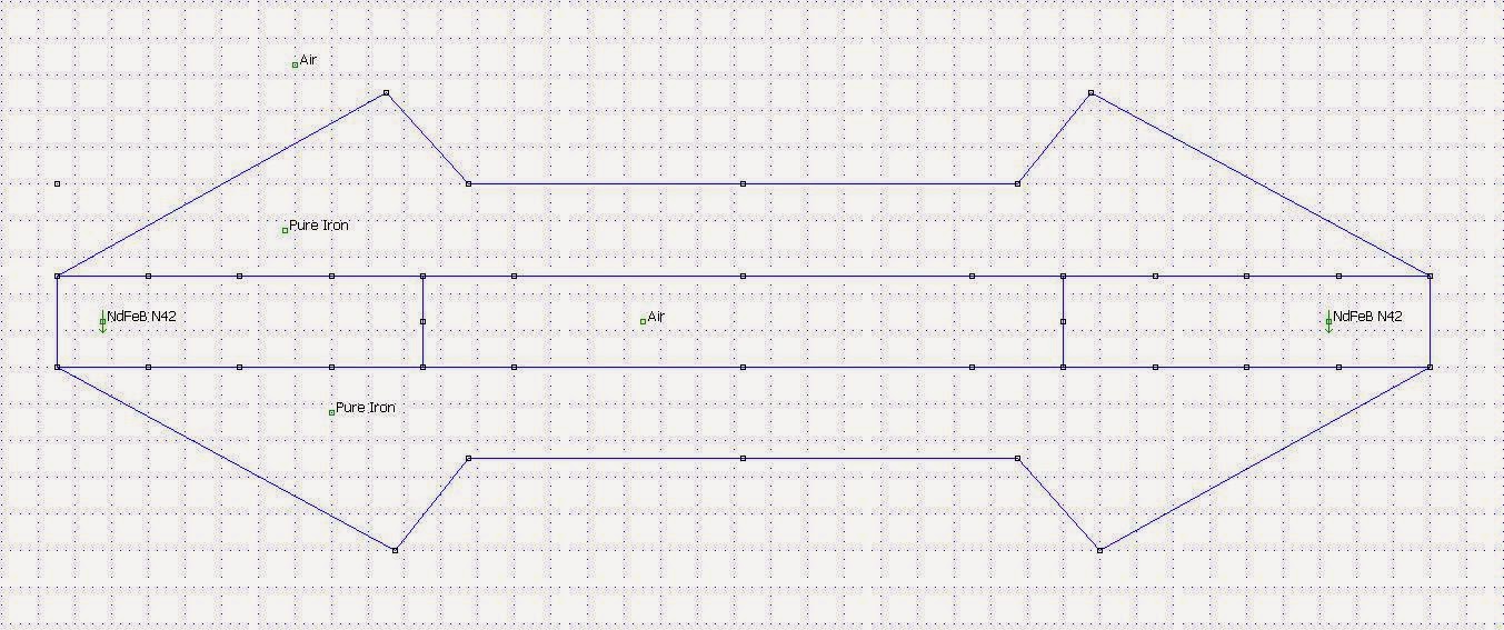
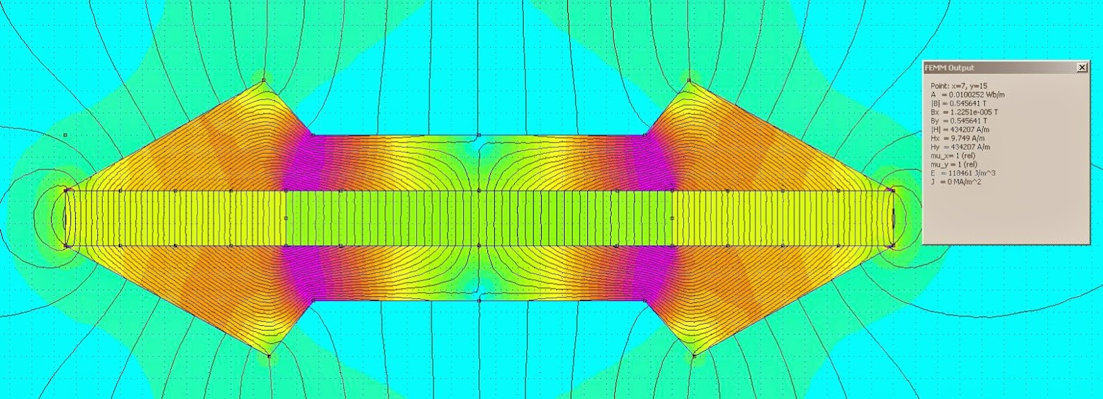
The magnetic flux density is 0,55 T in the gap.
Without making the grid (5 mm iron every 10 mm) any deeper than the 10 mm shown, what can be done to increase the magnetic flux density further?
Hi solhaga,
Your AMT's look truly great")
I recently had a chance to hear a mid AMT driver, and I was quite surprised how much different it sounded in the 300-600 Hz range relative to a conventional cone driver. The AMT was just significantly clearer and detailed. However, I am bit concerned about whether this comes at a cost with regards to 'weight', 'punch' and 'dynamics', so my question is:
When you lowered the crossover point from 400 Hz to 250 Hz between the AMT and the AE TD15's, do you think you loose anything with regards to 'weight' and 'punch' in the sound?
Thanks a lot - and keep up the good work!!
Best regards
Peter
Your AMT's look truly great
I recently had a chance to hear a mid AMT driver, and I was quite surprised how much different it sounded in the 300-600 Hz range relative to a conventional cone driver. The AMT was just significantly clearer and detailed. However, I am bit concerned about whether this comes at a cost with regards to 'weight', 'punch' and 'dynamics', so my question is:
When you lowered the crossover point from 400 Hz to 250 Hz between the AMT and the AE TD15's, do you think you loose anything with regards to 'weight' and 'punch' in the sound?
Thanks a lot - and keep up the good work!!
Best regards
Peter
That was exactly the reason for me lowering the Xo.I recently had a chance to hear a mid AMT driver, and I was quite surprised how much different it sounded in the 300-600 Hz range relative to a conventional cone driver. The AMT was just significantly clearer and detailed.
It is quite easy for me to test. Do you have an example on what to listen to?However, I am bit concerned about whether this comes at a cost with regards to 'weight', 'punch' and 'dynamics', so my question is:
When you lowered the crossover point from 400 Hz to 250 Hz between the AMT and the AE TD15's, do you think you loose anything with regards to 'weight' and 'punch' in the sound?
Hi Solhaga,
Thanks for responding! With regards to music, I mostly listen to rock music and at some point I had AER MD3 drivers in Oris 150 front horns. This combo sounded incredible on acoustic recordings and female voices, but when listening to classic rock music (e.g., Pink Floyd, Jethro Tull, Porcupine Tree, or Red Hot Chilli Peppers) they tended to sound somewhat 'thin'.
Do you think the increased resolution/clarity when lowering the crossovers point comes at a cost with regards to 'punch' and 'weight'? I'm sorry about all the subjective terms, but this is probably the best way I can present the question...
Best regards
Peter
That was exactly the reason for me lowering the Xo.
It is quite easy for me to test. Do you have an example on what to listen to?
Thanks, I hope my escapade into planar bass will eventually pay off for the AMT.Hi Solhaga
Welcome back on the AMT scene.
Bernt
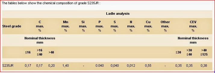
I'm using 5x40 mm bars of this steel as the base material:.
You could use pure iron 99.9% Armco iron.It can cary 2,1 T.
Thinner field ,narower field .Longer to keep the surface areal.
Effective sound generating area will be 60x300 mm.What size are your diaphragm.
That is roughly 340x300 mm unfolded.
You can divide the field in 2 ,side by side.
[/url][/IMG]
Here 2pc. 10x30mm. 0,5T. with standard steel.
Bernt
Thanks for the suggestion. But one of the requirements for Mk II is that it shall be only one membrane. There are two now in Mk I (Well it wasn't Mk I until now).
What's the benefit of having two membranes side by side?
Here a 70mm gap.
 [/url][/IMG]
Field is 0.3T. and iron max is 1,95T.
2x30mm
field is 0,5T. and iron max is 1,5T.
I have nice results with my new membranes only 40mmX80mm 8,5mm Deep.
I don't think length and width the most important to get low freq.
Pleat depth(weight) and compliance matters more.
I use 10my alu now .
Bernt
Field is 0.3T. and iron max is 1,95T.
2x30mm
field is 0,5T. and iron max is 1,5T.
I have nice results with my new membranes only 40mmX80mm 8,5mm Deep.
I don't think length and width the most important to get low freq.
Pleat depth(weight) and compliance matters more.
I use 10my alu now .
Bernt

- Status
- This old topic is closed. If you want to reopen this topic, contact a moderator using the "Report Post" button.
- Home
- Loudspeakers
- Planars & Exotics
- Yet another DIY AMT