Testing low current diodes for fault current survivability
Hi Ian,
would you be prepared to do me a big favour?
Unplug from the mains.
Wire a temporay dead short from mains live to audio ground (not safety ground, a suitable point would be the speaker return terminal or one of the ground lugs on the amp PCB).
If you prefer you can disconnect the amplifers from their supplies.
Plug in and momentarily switch on.
Switch off.
Unplug from the mains and open up.
Measure your disconnecting network to see if it has survived.
Tell us the result.
I'm too much of a wimp to try it for you.
Hi Ian,
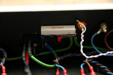
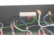
thanks to Keltic I can see that you have the safety earth and the disconnecting network both attached under the same securing nut.
I would recommend that you first fix the safety earth under it's own nut. and maybe even double nut it to remind you to NEVER take it off.
Then attach the disconnecting network with it's own fixing nut.
This way if you or a maintenance technician start to experiment with the audio ground the chassis remains safe. Remember the rule :- the safety earth MUST be PERMANENTLY fixed to all exposed conductive parts. We cannot easily weld (NOT soldered), so bolted is the next best solution.
Hi Andrew,
As much as it would be fun to potentially destroy a lot of hard work, I think I might give the live mains test a miss. If I had some spare parts I might be tempted, but as it is the only parts i have are in the box now and installed in the hifi rack, all neatly wired up and sounding great!
By the way, they are 6A diodes, so hardly small!
Keltic, thanks for brightening the picture.
If I were you, I would do a bench test with some spare components, unless you really want to risk killing your amp. 
As for your other comment about the safety earth, i am unlikely to be doing much fiddling now, other than to add some bitumen sheet to the lid to stop it ringing.
As for your other comment about the safety earth, i am unlikely to be doing much fiddling now, other than to add some bitumen sheet to the lid to stop it ringing.
well I tested it.AndrewT said:Hi,
I am using paralleled 35A power diodes (70A cf 6A). Hoping they will withstand a short term transient current up near 1000Apk.
Maybe I will just pluck up the courage to live test my audio to safety earth network.
Wired an IEC input socket/filter with the disconnecting network across Live to Neutral.
This is a double switched and double fused IEC socket, with both poles fused.
Put a T6.3A in the neutral line and T4A in the live line.
35A bridge cross coupled to run the diodes in parallel
10r 5W across one pair of terminals, 100nF ceramic across another pair and 12r 600mW metal film across the third pair (low inductance bypass). Earthing (Grounding) Your Hi-Fi - Tricks and Techniques fig3.
Switched on at the wall socket with the IEC switch off. Nothing.
Switched on with the IEC socket in the ON position.
Besides the bright white flash and the enormous bang that sent the fuse holder shooting across the room, not much else happened. All the disconnecting network components are intact, no heating, no discoloration and all measure correctly.
Surprisingly the T4A fuse survived, the IEC socket has some burnt terminals around the fuse locations. The T6.3A fuse has gone, except for one end cap still in it's holder. Everything inside the fuse compartment is blackened. No idea what it did to the RF attenuator parts??
Seems that the 35A bridge version of the disconnecting circuit can survive a close rated fuse (T4A) for upto 1kVA transformer on 240Vac
Last edited by a moderator:
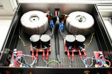
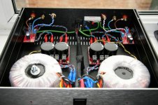
ianpengelly. I have just built one of the Chipamp kits. Running on one PS at the moment (but I built two for pure dual mono) I have ordered another tranny, but are intrigued as to how you ran both boards off what appears to be a dual secondary tranny. Did you just daisy-chain the secondary's from one board to the other?
Hi Puffin,
I just split each of the secondaries to wire up two PS boards, but like I said in my commentary it wasn't ideal because of the hum.
Andrew,
Nice work, a video would have been interesting to show what happened... I am slightly concerned that your fuse holder took off across the room!
I just split each of the secondaries to wire up two PS boards, but like I said in my commentary it wasn't ideal because of the hum.
Andrew,
Nice work, a video would have been interesting to show what happened... I am slightly concerned that your fuse holder took off across the room!
Update
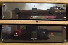
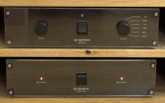
I got round to replacing the front on my chipamp and my preamp, as they didn't really fit in with the rest of my gear with the silver fronts and also I had used pencil to indicate what the knobs were for on my pre-amp... classy eh?
Anyway, I decided to borrow an idea I had seen used for some speaker lables by someone on this site and use two sheets of perspex with a printed lable sandwiched between them to give the results I was after and here they are!
Attachments
Can we see some pics of the inside of your pre-amp and how you propose to go active with it ?
As you may remember I built a dual mono BrianGT amp. I have since made a P2P 3886 using Nuuk's excellent site (and his help on here !). Even made my own snubberised PS. Trouble now is I have two great sounding amps ( I used to have Audiolab per/power), but the one I slaved over for hours is the one that is running now !
I am using a valve pre, which semms to suit it very well. It has a lot of gain.
I'll try and get some photos next time i have it open to wire up the later three inputs, as only the CD, Tuner and TV are wired in a the moment.
I am planning on building a buffer based around the OPA627 to make it active, with a regulated PS. There are a few designs out but this is the one I am most likely to follow:
http://www.platenspeler.com/diy/preamps/uk_gainchooser_3.html
If you have two amps, why not bi-amp? Or go surround sound, or use one with your PC as a second system? Lots of possibilities.
Is your valve pre one you built or bought?
well I tested it.
Wired an IEC input socket/filter with the disconnecting network across Live to Neutral.
This is a double switched and double fused IEC socket, with both poles fused.
Put a T6.3A in the neutral line and T4A in the live line.
35A bridge cross coupled to run the diodes in parallel
10r 5W across one pair of terminals, 100nF ceramic across another pair and 12r 600mW metal film across the third pair (low inductance bypass). http://sound.whsites.net/earthing.htm fig3.
Switched on at the wall socket with the IEC switch off. Nothing.
Switched on with the IEC socket in the ON position.
Besides the bright white flash and the enormous bang that sent the fuse holder shooting across the room, not much else happened. All the disconnecting network components are intact, no heating, no discoloration and all measure correctly.
Surprisingly the T4A fuse survived, the IEC socket has some burnt terminals around the fuse locations. The T6.3A fuse has gone, except for one end cap still in it's holder. Everything inside the fuse compartment is blackened. No idea what it did to the RF attenuator parts??
Seems that the 35A bridge version of the disconnecting circuit can survive a close rated fuse (T4A) for upto 1kVA transformer on 240Vac
So, as I have read so far, that would be the correct implemention for a completely safe device? It would be lovely to have a clearer, more detailed description of the component and their position (schematic, here). I'd be glad to implement it in my build right now and I would gladly report all of it in detail in the form of a HOW-TO for futur builders!
Last edited by a moderator:
You can find it all discussed at length here with the schematic about three quarters of the way down the page
Building a Gainclone chip amp power supply.
John
Building a Gainclone chip amp power supply.
John
- Status
- This old topic is closed. If you want to reopen this topic, contact a moderator using the "Report Post" button.
- Home
- Amplifiers
- Chip Amps
- Yet another 3886 gain clone!