well i built my first amplifier - Progect 3a
it is working but here are some problems:
1. when i disconnect the input signal, its starting to make noises from the speaker (bzzz..)
2. the volume trimpot isn't working, the amp is always at full volume.
3. when the pot stands at max resistence the vol. is still maximum...
but when i switch to minimum resistanse the volume dont change
but it makes some noise form the speakers and the temperature of the output transistors starts to increase VERY fast
PLEASE HELP MEEE!
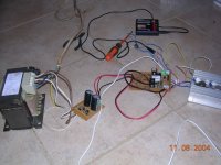
here is the pic: (ITS STILL MONO, NOT FINISHED MAKING STEREO YET, NOT FINISHED MAKING A BOX...)
it is working but here are some problems:
1. when i disconnect the input signal, its starting to make noises from the speaker (bzzz..)
2. the volume trimpot isn't working, the amp is always at full volume.
3. when the pot stands at max resistence the vol. is still maximum...
but when i switch to minimum resistanse the volume dont change
but it makes some noise form the speakers and the temperature of the output transistors starts to increase VERY fast
PLEASE HELP MEEE!
here is the pic: (ITS STILL MONO, NOT FINISHED MAKING STEREO YET, NOT FINISHED MAKING A BOX...)
Attachments
Umm, if you're referring to the trimpot VR1 in the schematic, that's not a volume pot. That's the output bias adjustment. And yes, if you turn it too far in one direction, things will get hot VERY FAST! 
Hum when you disconnect the input is normal for laying out on the floor like that (it's stray noise pick-up).
Hum when you disconnect the input is normal for laying out on the floor like that (it's stray noise pick-up).
Assuming you're not pulling my leg, the output bias is simply the idle current through the output transistors with no signal applied. If the current's too high, things get hot rather quickly (there may be a "bang!" at some point), too low, and the distortion goes up. There should be a recommendation somewhere in the literature for your amp design on setting this.
you need to add an input resistance from input to ground, in front of the input coupling capacitor, C1. Tis probably why the circuit makes noise when the input isn't connected; the output impeadence of your pre-amp is the input resistance when it is connected.
you might try to add a current source for the VAS stage instead of R9 & R10.
Try connecting a couple of power diodes, 1A in series from the base of Q5 to base of Q6. Power diodes have a larger forward voltage, but with control of the bias servo Q9, these diodes would form a "latch" to keep the outputs from having to large DC bias. Also, when one transistor conducts it will push the other into cuttoff so not as much heat would be produced.
Also, you should put the circuit in a metal enclosure to sheild from any stray RF noise that may bounce around in your circuit and cause undesirable effects.
You should setup the bias as written in the article, then check for DC voltage on the output.
Ideally use some dummy speakers or resistors to test the amp for at least a little while before you connect your beloved speakers.
It may seem a stupid advice but it isn´t; I´ve seen a good friend being in the same situation as you, being as happy about his new amp as he was angry about his burnt voice coils.
Congratulation to your amp. Quite amazing for your age.
Cheers
Benmanf,
Q9 is the bias servo. it should be mounted to the heatsink with the output transistors. The operation theory is: because a BJT tends to conduct more when heated, the bias for these devices is different at low temperature than at high temperature. It takes less Vbe to turn them on when hot. So your bias circuit has to have a dynamic responce to heat. As the outputs get hot, they heat the servo transistor and cause it to conduct more, turning the outputs off more. The idea is to get an overall temperature coefficient of around 1. If the servo isn't mounted with the output transistors, then it is kind of useless and the outputs will go into thermal runaway. (bang!!)
To set your output bias, remove the speaker or load resistance, and measure the voltage accross R13 & 14. Adjust the trimpot VR1, to saturate Q9, turning the outputs off. You should see 0V accross these resistors. slowly turn the pot on until you just begin to see voltage. This is where you want to bias the outputs.
If your DC bias is not 0V, I would suggest changing R2 from 22K to 20K and add a 5K pot in series with it. Even better, get a 15 or 20 turn pot for more accuracy. This will allow you to fine tune the DC bias on the output.
You seem to have a pretty good grasp on things, just some minor technicalities.
PS: If the hisssssssssss is to overbearing try putting a small capacitor say 10-50pF from collector of VAS transistor(Q4) to the base of Q2.
Bias is small current that keep transistor on.
Transistor need around 550 to 700 milivolts DC, measured from base to emitter.... one voltimeter point to base and the other to the emitter.... if low than 500, normally no current flow.... and if high the transistor conducts maximum current....his internal resistance reduces, and the electron flow is enormous.
You can understand alike one automobile engine iddle, engine running and 1000 RPM ... in stand by, waiting the green signal to acelerate.....
This is measured over the emitter resistors, using voltimeter and ohms law... you measure the milivolts over the emitter resistor and divide this value, expressed in volts by the resistance you use, expressed in ohms.... example:
Measured 20 milivolts over 0.33 ohms resistors.
0.020V divided by 0.33 ohms 0.020/0.33=0.060A....
the result is expressed in amperes.... so... 60 miliamperes.
Have to check the other resistor too.....negative and positive rails.
And use the trimpot to adjust....
Too much bias... to great current, will result in amplifier overheat, and will be hot in stand by mode (no signal) too.... working will overheat a lot!... can distort too much, and will reduce the output power too.
too low the bias.... amplifier will distort low volume... will be cold, and will work good in medium and hi volume.
Trimpot to volume, or potenciometer..... extremes will go , one to earth and other to signal input.... the signal entering amplifier... the center tap will be to amplifier input condenser.
by Ben
Carlos
 i made a critical mistake!!!
i followed the instructions for setting the bias and somehow when i tested the voltage i tuched some thing and it maked a little spark and the speakers started to make noise...i checked the fuses and one of them was 'dead', i replaced him and applied the power, then the second fuse burn....
what can go wrong? (i have some replacement parts)
This is more common than you can imagine
We all do this....but only few people has courage to tell.
Congratulations!
If you not skilled to measure transistors....better to change them all.
You have burn some of them.... others not.
Better than to spend time, now, to learn how to test them... to replace them all.
Late, without this damn feeling, calm, you will easy learn how to test them.
"one ohmeter test, adjusted to diode position, the red point in the base.
Now touch the colector and touch the emitter.... they have to be consistent in conduct both, or not conduct both.
Invert the points....now have to be consistent... conducting both or not conducting both.
Those two tests must show you different results....if the first showed you conduction, the second will not conduct.
If the second show you conduction, the first will not conduct.
Now test emitter to colector...cannot show resistance...cannot have conduction of energy... now invert the leads, also cannot show conduction too... from emitter to colector...or from colector to emitter never conduct!"
do not worry, and be happy... i done it around 3000 times in my life.... i am destroyer X, the best, the greatest earth transistor destroyer... you are loosing..... have not chance to reach my points!! hehe
Carlos

WOW I THINK YOU RIGHT...
ARTICLE
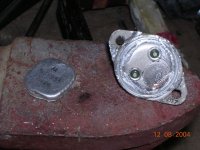
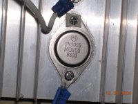
IT LOOKS LIKE A FAKE
BUT MY 3055 LOOKS LIKE MOTOROLLA'S REAL ONE
THOSE ARE NOT A FAKE:
ARTICLE
IT LOOKS LIKE A FAKE
BUT MY 3055 LOOKS LIKE MOTOROLLA'S REAL ONE
THOSE ARE NOT A FAKE:
An externally hosted image should be here but it was not working when we last tested it.
- Status
- This old topic is closed. If you want to reopen this topic, contact a moderator using the "Report Post" button.
- Home
- Amplifiers
- Solid State
- Yay!!!!!!my amp is complete and working!...but...--->