Something sprang to my mind just now, you use a ECC83 as a buffer and I can’t help thinking that a ECC 88 could be a more appropriate choice there. The output impedance (or resistance, I keep messing ‘m up) and the drive capabilities seem better used to this role of buffering the RIAA sage you described. What do you think about this? And, if feasible, how would you implement this? For example, the heater voltage is 12,6V and the ECC88 uses 6,3V. As you guess, I’m not good in theory but I can solder pretty well though.
Again, thank you in advance, Stef.
Again, thank you in advance, Stef.
The 3 x ECC83 works very well, hundreds have been built and in the design the ECC83 is OK as a buffer. I have tried ECC81, ECC82, ECC85 and 6N1 without any benefit and the ECC83 always seems to give the best 'sparkle'. Stef, the design is not meant to be the worlds best. It exists as an extension to the now defunct WAD design to turn the MS22/23 into something that delivers much better sound, whilst not detracting from the RIAA characteristics. The present Yaqin arrangement provides enough heater voltage to allow a 7812 regulator to provide 12V at a current of 450mA. This is an estimated power dissipation in the regulator of 1.35 Watts with something like a small 75degC/Watt heat sink. If you fit an alternative regulator to give 6.3V at 900mA then the dissipation will rise to 7.83 Watts. The heat sink will now have to be a very much larger 12.5degC/Watt so it makes sense to keep to a 12V regulator as fitted. I have built many versions of the design and one used 6.3V with a suitable power transformer to keep dissipation down though I used a Darlington Power Transistor to do the regulation. Before you disparage the design any further, perhaps you should do the conversion first. Take a listen to the result, then perhaps you may come to the same conclusion as many others including myself that further changes are not necessary. It will 'Put Life' into the present stock unit to provide more than enough listening satisfaction - Guaranteed. 
Thank you Les for your explanation!
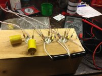
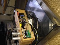
As I have a scrapped MS 12b I was quite interested in the alteration of that phonostage. And re-using so much could keep my investments down. Hurrah! And I had some different parts around so I took the plunge and today I have started my first very own build and I love to mess around with this. I decided to make a test-unit (made of an old wooden winebox) This first stage is the result, there is still a lot to be done. High tension, heaters, earthing, etc. etc. I am a starter, I have read a lot but I only just swapped parts a bit so I have to learn a lot. But thank you very much for making me very enthousiastic again!
Cheers, Stef.
/Users/phats/Downloads/foto-2.JPG
No screening will be provided by the wood enclosure so take care with the input wiring. Remember the circuit will be boosting low frequencies of which of course is the power 50/60Hz. The MS12 should be capable of conversion as the circuitry is the same as the MS22/23, however the board layout may be slightly different.You would have to give up one of the valves in the rear position as a cathode follower for the RIAA unless you fit a MOSFET which is not as good as having an extra valve here.
Not finished, just a mock-up. Having difficulties in deciding where to terminate power (B+ and heater) ground and noticing a black lead from the secundary side of the Yaqin transformer. I am not sure what to do next, does anyone have an idea? The circuit'side' is finished, really happy with all the little stuff I collected over the years and the fact I could put the left-overs from the MS 12b to good use... Fun in soldering!
Attachments
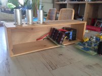
Hi Les, nice of you to chime in! Ofcourse I am a little apprehensive of the wooden-box, but it was just meant as a testbed. Results could be negative if lots of hum are picked up, I hope I did everything as it should be, as I just mentioned I really have no idea where to terminate power-ground. I am building your complete tube version (based on the WAD phono amp, btw. I loved that magazine of old!). I just used up all the old Yaqin stuff that was needed. I hardwire everything, so I don't have to consider the old MS 12b layout. If all works well the trick will be creating a useable enclosure, I love wood, but in this case that might not do the trick. I haven't thought that one out yet.
Cheers, Stef.
Cheers, Stef.
The 'odd' Black wire coming from the transformer is probably the Ground for the transformer frame. Your construction looks almost like my very first creation but inside a die cast box. I think in that I commoned both INPUT RCA's together and connected all Ground connections there. I read somewhere that the input connections is where the common Ground point should be.
Hi les,
That is what I am reading as well, all grounds 'meet at the input jack'. Since, for now, I am hardwiring the turntable output-cables, I suppose I have to terminate my B+ and heater ground at the 'loose-end' of the earth-bus as well... Do I have to solder that black wire to earth in the mains-input or shall I solder it to the earth-bus? Thanx for your input!
Cheers, Stef.
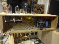
I finished the phono amp this morning, B+, heaters and grounding and I decided to mount inputrca's as well. If only for stable ground-posts. I had a unexpectedness at start-up. There are two heater circuits, one is regulated, this one gives a nice 12,6V. The other one is a simple CRC circuit, but puts a whopping 16V's into the buffertube.
The RIAA tubes immediately flared, perhaps its cap's related (bad caps, bad tubes, inrush, I do not know) but the buffertube at that high voltage kept glowing (a little bright perhaps!).
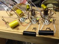
The resistor is the big one (15 ohm, 7 watt) and it brings the 18V(after the rectifier and first capacitor) down to 16V, too much.
I connected the regulated heaters to the RIAA tubes and the unregulated to the buffer circuit (I thought that as less critical).
The CRC is as follows; 12.000mF-15 Ohms-12.000mF and the regulated; 12.000mF-7812 reg-3300mF.
Those caps were surplus Nippon Chemicons and the stock caps from Yaqin felt too flimsy, so I swapped those parts.
I hope someone can help me out a bit, as for now try to measure different things, but I am unsure how to measure. I made a cable with a 1K5 resistor for discharging caps and I suppose I should select amp-settings on the meter, but I could't even measure a current on a charged cap. So probably I am doing everything wrong (of-course) so some practical advice wouldn't go amiss!
Cheers, Stef.
The RIAA tubes immediately flared, perhaps its cap's related (bad caps, bad tubes, inrush, I do not know) but the buffertube at that high voltage kept glowing (a little bright perhaps!).
The resistor is the big one (15 ohm, 7 watt) and it brings the 18V(after the rectifier and first capacitor) down to 16V, too much.
I connected the regulated heaters to the RIAA tubes and the unregulated to the buffer circuit (I thought that as less critical).
The CRC is as follows; 12.000mF-15 Ohms-12.000mF and the regulated; 12.000mF-7812 reg-3300mF.
Those caps were surplus Nippon Chemicons and the stock caps from Yaqin felt too flimsy, so I swapped those parts.
I hope someone can help me out a bit, as for now try to measure different things, but I am unsure how to measure. I made a cable with a 1K5 resistor for discharging caps and I suppose I should select amp-settings on the meter, but I could't even measure a current on a charged cap. So probably I am doing everything wrong (of-course) so some practical advice wouldn't go amiss!
Cheers, Stef.
Last edited:
So, one reads voltages on a cap, discharging was very easy with isolated croc-clips and that inserted resistor and in a short period of time the meter a very lowish number, 1V or such... test probe, no arcs, so deemed safe and indeed I could go on. I redid the heater circuit, dumped the unregulated part of it and connected the buffer-tube to the 7812. With a restart the buffertube, instead of the RIAA tubes, flamed-up. But after 'glowing-down' it stayed, so power-off. And a little while later a restart and all tubes came up normally, testing and a sound 12,45V! Why I just didn't heat all the tubes via the 7812 I really don't know, probably blindly copying the old Yaqin circuit. Quite stupid of me... Another part of the Yaqin circuit (MS12b) is the B+ which is not a preferred 244V but a lower voltage of 233. I will have to replace the last dropping resistors to a value which gives me the 244V, I'll figure that out yet...
Cheers, Stef.
Cheers, Stef.
Hmm,
Well, all in all it doesn't work yet. Calculating the last resistor in the B+ caps was not succesful, instead of a 10K I calculated a 3K5 but he B+ did not change at all. It stayed round 233V, don't know how that can be. Just for testing I hooked it up with an old thorens and there was lots of humm, really loud! But! There was music as well, so it works a little bit. But for now I am a bit disheartened. I am not sure what to do next. Except for starting over again and now in a metal box. Who knows, it'll turn out better! This is definitely harder then I thought!
Cheers, Stef.
Attachments
- Home
- Source & Line
- Analogue Source
- Yaqin MS-22b Phono Amp