Hi,
Okay see if you can read these pins voltage to see which one it is causing the problem. You can do the check with the 168 out.
mcu pin 36 = PRD DC protection should be 0 = good 1 = fault detected
mcu pin 35 = PRV V protection should be 0 = good 1 = fault detected
mcu pin 44 = PRI I protection should be 0 = good 1 = fault detected
I have seen a few "different" Yamaha receivers with similar problems and they all had the same bad part. You can try it anyways. EEVBlog #379 - Yamaha RX-V557 Receiver Fix - YouTube
@Tauro: I will try, that chip is in the board that doesn't have a very good access point, I dont know hot to get at it right now, but I will work on it.
@Lanchine: That cap isn't my issue. Removing the Q168 makes it come on and stay on. With q168 in, it will not even turn on.
I in fact powered it up without that cap in at all without Q168 in the circuit. It came on and stayed on.
Cool.
Srinath.
@Lanchine: That cap isn't my issue. Removing the Q168 makes it come on and stay on. With q168 in, it will not even turn on.
I in fact powered it up without that cap in at all without Q168 in the circuit. It came on and stayed on.
Cool.
Srinath.
Hi,
You can check PRD , PRI and PRV at the CPU Board function 1 connector P-86. A-7 Page 64. Any one reading +5 will caused not to power ON or close the power relay.
We need to check does 3 signals to be able to find out why does not power ON.
I am working on a block schematic to figure out how to check which channel it is causing the error. There are two check that the system does. One it is the dc voltage output at power ON and the second check for high voltage output.
Sorry, I have been asking too much checks.
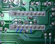
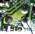
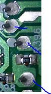
The receiver is nearly 15 years old. I suspect you will have to visually inspect for broken solder joints. If the mcu is near the display, then it's solder will have to be redone.
This is the first thing I do when repairs of such items are required and many get repaired just by soldering.
Pictures of bad solder attached for reference.
Gajanan Phadte
This is the first thing I do when repairs of such items are required and many get repaired just by soldering.
Pictures of bad solder attached for reference.
Gajanan Phadte
Attachments
Hello Gajanan, How you doing. I've not heard form you since early last year I think.
This amp does not power up when the 2SC5200 in location Q168 is soldered in. No matter what else is removed/installed, doesn't matter. If Q168 is in the circuit, no power on. It clicks on and off immediately. Ive swapped the 2SC5200 from another location (Q175) in Q168, and it doesn't power up then either.
The Q168 being empty, the amp powers up, and display lights and it even goes into diagnostic mode. It also makes sound from 1 channel. It behaves like a flawless receiver, except it has no power in 1 channel.
I dont think its a solder joint. I think its something in that Q168 circuit. I will be tearing into it later today. I will look for burnt components and for solder joints too. BTW I did find bad solder in one little transistor and I thought a little burnt ... I will look into it again, its covered by the rear amp board.
Thanks.
Srinath.
One crude way to test for the power amp output having a high DC offset is as follows...
Connect a DMM to the PAmp output(not on speaker terminals) using clipons with the amp mains OFF. Now put ON the mains observing the DMM. If you see the signs of rising dc voltage on any of the PAmps, then that amp is faulty and needs to be rectified. Do it for all the PAmps to find out the faulty channel. Check for all the PAmps as there is no guarantee that only one will be faulty.
If no DC offaset fault, then u will have to look for other two conditions as mentioned by tauro0221.
Edit: I noticed u have mentioned abou Q168 removed...and it powers up
Now do one thing. Remove the mains and wait till the caps discharge.
There are two identical amps in front of you, measure resistance between identical locations on each amp and compare. Ignore small differences which can be due to component tolerances. Wherever it shows big difference, mention where.
Just measure across any component from any easy side of the pcb.
Gajanan Phadte
Last edited:
The Q168 being in the circuit, the amp never even flashes on. Click, click, nothing lights up.
Q168 removed, it come on and works in 1 channel. The Q175 being put in place of Q168 and it doesn't power up either.
The main caps discharge test ? OK then I need to solder Q168 back in and test things for resistance ? I'll try it in a bit.
Thanks.
Srinath.
Q168 removed, it come on and works in 1 channel. The Q175 being put in place of Q168 and it doesn't power up either.
The main caps discharge test ? OK then I need to solder Q168 back in and test things for resistance ? I'll try it in a bit.
Thanks.
Srinath.
Hi,
Inline with gmphadte comments in thread 91 there it is a simple check that I do but I do not know if your voltmeter can read AC. By selecting the AC mode you can read the rail voltages to see if you have bad capacitors. They should read almost zero volts. Any high voltage reading means that the capacitors are bad and need replacement. It is a simple test when you do not have an scope. If you have an scope then it easy to check if any of the voltages have ripples indicating bad caps. Follow gmphadte check and if you do not find anything proceed to check the voltage with voltmeter in AC mode.
Inline with gmphadte comments in thread 91 there it is a simple check that I do but I do not know if your voltmeter can read AC. By selecting the AC mode you can read the rail voltages to see if you have bad capacitors. They should read almost zero volts. Any high voltage reading means that the capacitors are bad and need replacement. It is a simple test when you do not have an scope. If you have an scope then it easy to check if any of the voltages have ripples indicating bad caps. Follow gmphadte check and if you do not find anything proceed to check the voltage with voltmeter in AC mode.
Same amp ... similar problem .. not the same
I have the same amp ... won't power on .. no display ... zilch
testing around shows that the power on button is good. The standby power supply only delivered 4.8 volts .. schematic shows 12.5 .. That voltage goes straight to the control board. Disconnecting the lead to the control board allows the standby voltage to rise to 16.5 volts
Disconnecting everything else from the control board has next to no effect on the low voltage. .. In other words, the control board draws the voltage down all by its self. IC4 is the regulator there that gets the voltage and is supposed to drop it down to 5.7v
IC4 gets warm and so does the cpu on the board. .. but not hot .. apparently there is not enough power in the supply to get things hot. So anyone think we are looking at a short or near short internal to the cpu and that it's toast? If so, how to replace the board or acquire a new cpu? .. Obviously, soldering a new one on will be a beastly job requiring hot air and flux .. I might have to order some of that transparent flux for that kind of job as the yellow sticky stuff seems like it's too gummy for this kind of fine soldering.
I'm not sure if this is the same issue, but there's a common problem with a polyester cap in the supply that causes them not to power up.
https://www.youtube.com/watch?v=MwvjAtSr5t8
https://www.youtube.com/watch?v=MwvjAtSr5t8
this unit does not have that same board/cap .. and the cpu chip has a pin that is clearly shorting the standby power supply to ground. Also, the input coil of the standby power supply is 750 ohms, so I think something is wrong with that as well as I believe it should be closer to 150 ohms. .. unless they have intentionally built a current limiter into that transformer.
there is a film cap on the power supply line however.. a green one .. it may be doing the same thing. .. But the output of this supply is supposed to be 12.5 volts rather than 5 .. The regulator is on the control board .. dropping it to 5 volts .. I hope it's not smoked because of overcurrent .. something I'll have to watch out for.
- Status
- This old topic is closed. If you want to reopen this topic, contact a moderator using the "Report Post" button.
- Home
- Amplifiers
- Solid State
- yamaha rx-v2095 wont power on