Trying hard to come back to tube amps after some busy time since my last build (RDL by SY). I had collected a lot of tubes and decided to build something easy, small. Must be SE, parafeed and with Po not more than 10W. I have Svetlana 300B, 6C4C, C3g, 6H9C, 6C4Pi, 6C45Pi among others (GM70 as well, but still too little place to build such monster and too scared).
Ok, I am designing C3g+300B SE Parafeed with LEDs in cathodes.
I would like to read your opinions on the posts while making progress.
TIA
Ok, I am designing C3g+300B SE Parafeed with LEDs in cathodes.
I would like to read your opinions on the posts while making progress.
TIA
Operation point
Found a reply on another forum regarding C3g and 300B from Thorsten Loesch: Tube DIY Asylum - Re: C3g as driver for 300b
I initially wanted to go 390V/60mA/-61,5V - and there is 430V/80mA/-77V in the post. The only 300B I have are 2 matched (?) SV300B from Svetlana Electron Devices Inc. (Made in Russia) dated Dec 2001. The parameters shown: Ia = 57|58 mA and S = 4,7|5,0 respectively. I wonder what was Ua...
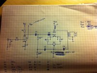
Schematic - first approach
I think of replacing R3 with CCS in the future.
... and convert C3g to triode connected, of course.
Started some output stage simulation with LT Spice. It seems that OP xformer params are critical to bandwitdh. And there goes the question: a transformer is represented by a couple of parameters, one of them is K coefficient - what is a good method to measure one in practice? My transformers were wound a few years ago and there is no chance I can find specs.
A critical factor in a parafeed stage is the type of core you have in the OPT. The best type is the amrphous core because it doesn't store energy at low frequency. Never forget that decoupling cap + primary inductance = resonant circuit! The type of core is just critical as the cap.
45
45
Found a reply on another forum regarding C3g and 300B from Thorsten Loesch: Tube DIY Asylum - Re: C3g as driver for 300b
I initially wanted to go 390V/60mA/-61,5V - and there is 430V/80mA/-77V in the post. The only 300B I have are 2 matched (?) SV300B from Svetlana Electron Devices Inc. (Made in Russia) dated Dec 2001. The parameters shown: Ia = 57|58 mA and S = 4,7|5,0 respectively. I wonder what was Ua...
Be very careful with the SV300B from this era as they tended to develop intermittent shorts between the filament and grid. Hopefully these are the later version (series 3). FWIW these sounded great in PP, and not so good in SE. (SED furnished me with 8 of these for an amplifier design ultimately published in VTV, of these 6 ultimately failed.) I much prefer JJ 300B which have given great service for nearly 10yrs now.
How about fixed bias? Allows for very easy and rather revealing tuning of the operating point. It also eliminates some parts in the signal path at the expense of some additional (limited) supply complexity.
And the Ia listed in the matching data are relevant to the matching only, and with good ones you can run them at any current that stays below 90% of the rated dissipation, and I have found generally the hotter you run them the better they sound. (and the more power you get at a given thd %)
If you want a quiet amplifier heat the 300B with DC, and check out CCS based heating. Rod Coleman here has an excellent design just for this purpose.
Hopefully these are the later version (series 3).
How can I tell they are "series 3"?
How can I tell they are "series 3"?
I no longer remember the specifics unfortunately - you'll need to Google for additional information - probably specific date code range. I gave up on them 10yrs ago and haven't looked back.
Consider them as fodder for experimentation and if they are better than that consider yourself fortunate..
The tubes have the new logo: latin letter "S" not cyrillic "C".
BTW.
Your remark made me reconsider NOS 6C4C as an output triode.
They might be late enough not to have the issue.. Mine were either winged "C" or Svetlana branded.
I think the 6C4C might be a safer choice, it's basically equivalent to the 6B4G, note the maximum plate voltage is only ~250V (fixed bias -45V) for these types and you'll get maybe 3W out in A1.
I think the 6C4C might be a safer choice, it's basically equivalent to the 6B4G, note the maximum plate voltage is only ~250V (fixed bias -45V) for these types and you'll get maybe 3W out in A1.
Kevin the 6C4C can take up to 360V anode voltage and as far as I have seen (directly) up to 16-17W without any problem. It's an improved copy of the RCA design, IMHO. The higher plate dissipation actually stands also for NOS 2A3's and good quality chinese production (like Golden Dragon and Billington Gold which I think come from the same factory...). You can get easily 4W and up to 6W (in class A2 using a simple source follower).
Actually there are some old American amps which used the 2A3's at 22W plate dissipation! I cannot remember the name now...they were from DIYers
45
Last edited:
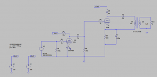
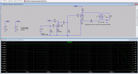
C3g + 6C4C parafeed with mains xformer as OPT - sim
Kids are at their garndmother, there was a national holiday in Poland and at last I had time to proceed with the work with an amp. The result is the below shown schematic.
On one Polish forum I found interesting discussion on using mains transformers as OPT. www.trioda.com • Zobacz w?tek - trafo sieciowe jako g?o?nikowe. I measured inductances of primary and secondary windings of one toroid mains transoformer (50VA / 230V / 9V). The values are shown on the schematic.
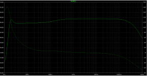
On the next picture frequency response is shown, as simulated in LT Spice IV.
I also simulated the circuit with LED biased 6C4C (4 x 26 LEDs), yet the outcome is not satisfactory. Still some analysis to be done.
Comments are welcome.
Kids are at their garndmother, there was a national holiday in Poland and at last I had time to proceed with the work with an amp. The result is the below shown schematic.
On one Polish forum I found interesting discussion on using mains transformers as OPT. www.trioda.com • Zobacz w?tek - trafo sieciowe jako g?o?nikowe. I measured inductances of primary and secondary windings of one toroid mains transoformer (50VA / 230V / 9V). The values are shown on the schematic.
On the next picture frequency response is shown, as simulated in LT Spice IV.
I also simulated the circuit with LED biased 6C4C (4 x 26 LEDs), yet the outcome is not satisfactory. Still some analysis to be done.
Comments are welcome.
Attachments
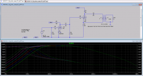
I am a bit confused: why those two circuits make such a difference? Only a cap position changed. 
Oh, and the OPT is not mains / power xformer. It is custom SE OPT: two primaries + two secondaries. In the schematics pris and secs are connected in parallel respectively.


Oh, and the OPT is not mains / power xformer. It is custom SE OPT: two primaries + two secondaries. In the schematics pris and secs are connected in parallel respectively.
Last edited:
- Status
- This old topic is closed. If you want to reopen this topic, contact a moderator using the "Report Post" button.
- Home
- Amplifiers
- Tubes / Valves
- yagoolar's tube amp projects