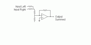
Hey, Al...would this AD SSM2141 per Fig. 3 on Page 6 work? Or do I still need to invert the "pre-amp"?
http://www.analog.com/UploadedFiles/Data_Sheets/SSM2141.pdf
http://www.analog.com/UploadedFiles/Data_Sheets/SSM2141.pdf
Yes...but in my application, I'm splitting the kit into two separate mono kits. I wanna build a retro cabinet with a single driver. The problem lies in that the iPod puts out a stereo signal thhrough its common ground 1/8" stereo jack and I need to combine them to drive the SINGLE LM3875. This thread started with the suggestion of a simple passive "resistive Y" to combine L-R positive signals but then Pinkmouse recanted because the Audio Sector kit is a non-inverting LM3875 kit. Supposedly this inverting vs non-inverting issue is the showstopper. It went on from there to highlight my ignorance and to set me on my path to discovery 
The most promising thing so far appears to be this SSM2141 chip but I'm still just marginally more savvy than when I started this thread.
ANY HELP IS APPRECIATED!
The most promising thing so far appears to be this SSM2141 chip but I'm still just marginally more savvy than when I started this thread.
ANY HELP IS APPRECIATED!
You may also want to check out the THAT 1250 chip. Mouser has them for $1.15 each.
http://www.mouser.com/search/ProductDetail.aspx?R=1250P08-Uvirtualkey61220000virtualkey887-1250P08-U
http://www.thatcorp.com/
http://www.mouser.com/search/ProductDetail.aspx?R=1250P08-Uvirtualkey61220000virtualkey887-1250P08-U
http://www.thatcorp.com/
That's for balanced lines Carlos, and is no good for your application. All you need is a basic opamp, and three 10K resistors. Two on the left and right input lines connecting to the -input of the chip, and one connecting between the -input and output. +input goes straight to ground. Simple. 
CarlosT said:Al...thanks...I'm still confused.
What happens in an OP amp if the feedback loop is switched from the negative to the positive input?
That is getting quite involved. If you want to know theory, your best bet is to download Walt Jungs's Opamp Applications from the Analog Devices website. He explains it much more lucidly than I could.
I read the Wikipedia stuff on virtual grounds and it's all fascinating stuff.
I just wondered how compatible Fig. 3 of the attached would be with the Audio Sector non-inverting LM3875.
http://www.analog.com/UploadedFiles/Data_Sheets/SSM2141.pdf
Fig. 3 shows a very neat summing circuit with zero external parts. The problem is that it's non-inverting.
Can someone please look at it besides just spewing patronizing wisdom? Thanks!
This was about the simplest (relatively) presentation on why one should go inverting on the channel sum.
http://www.forsselltech.com/summing buss.htm
http://www.forsselltech.com/summing buss.htm
Carlos,
I don't want to sound mean, but why ask a question and then ignore the answers? The simplest and most effective way to sum 2 signals, have volume control, and invert that signal is with the basic resistor divider mentioned back on page 1. I attached a schematic of the whole thing.
I don't want to sound mean, but why ask a question and then ignore the answers? The simplest and most effective way to sum 2 signals, have volume control, and invert that signal is with the basic resistor divider mentioned back on page 1. I attached a schematic of the whole thing.
Attachments
Bob0513 said:Carlos,
I don't want to sound mean, but why ask a question and then ignore the answers?...
Bob your answer from Page 1...the simple passive resistive Y would not work according to Pinkmouse because of the non-inverting schema of the Audio Sector LM3875 kit. The schematic that you just posted is closer to what appears to be the right answer but it basically took my grovelling for 4 pages worth of forum and countless hours of Googling to answer my own question. That wasn't too efficient.
I appreciate you hanging in there though and continuing to respond.
So after considering the mounting costs and complexity of using the SSM2141/INA134 buffer in front of the AudioSector non-inverting GC, I'm thinking of maybe using the Techdiy inverting GC kit instead.
Al et al. would you say that it's OK to just use the simple "resistive Y" to combine the channels then?
Where would you place the volume pot? I was eyeing up the spot where Jacknnj has the little trim pot.
Al et al. would you say that it's OK to just use the simple "resistive Y" to combine the channels then?
Where would you place the volume pot? I was eyeing up the spot where Jacknnj has the little trim pot.
Bob...I was trying to save the money and additional complexity of building another board and having to step down my 25+- supply down to 18V or 15V. Supposedly the original problem posed by Pinkmouse was that the non-inverting GC kit from AudioSector was not well geared towards taking combined channels.
- Status
- This old topic is closed. If you want to reopen this topic, contact a moderator using the "Report Post" button.
- Home
- Amplifiers
- Chip Amps
- Xtreme Noob - Summing Channels For Mono 3875
