I'm working on repairing my second of two Xtant amps. One channel (I believe the rear right) is not working, but the two front channels (at least) would work. There are twenty-four transistors along the main channel setup, 6 per each I believe. The rear right channel had 3 blown transistors of the 6, and one open resistor. It was showing as "OVER CURRENT" (yellow light) but the front channels would work anyhow. I replaced the 3 transistors, and and the burnt open resistor (the three resistors going to the transistors are removed in these photos, but they are there now), and when plugged in, the 3 originally blown transistors get hot as hell, and the other transistors (they're to the right and off to the side, I assume they have something to do with the power supply) literally screech and get very hot within 10 seconds (I have been running it on an ATX PSU, it can put out a max of maybe 10A on the high side before shutting down). OVER CURRENT still lights. Gain is turned all the way down, just as a bit of extra information. It looks like someone has already repaired something in here, two of the 'other' transistors (power supply?) have been changed. Several of the surface mount resistors had been changed as well. Where should I go from here? It'd be great to have a schematic, since it's a multi-layer board, but that's likely not possible.
As a side note, I have another broken one that appears to power up fine but does nothing, and the fan runs full-time. That one I believe got wet, so probably not best to start there, and is in much worse condition physically, but I have been using parts from it and I assume it is only something stupid that is wrong with it. I really want to get the one I am working on repaired. What sort of parts being bad would cause such rapid heat?
Also note, when testing it unless explicitly stated only ground, power, and remote (bridge from power) are hooked up; no speakers or input. I can keep shot-in-the-darking it, but I'd really like a directed search more. Any help would be greatly appreciated!
Here are a few pics of what I'm working with (note the burn marks are from the resistors, not me):
http://i.imgur.com/eu3COkT.jpg -- the white stuff is thermal paste
http://i.imgur.com/954k4dt.jpg
p.s. I know it looks like the left rear channel that is missing the pieces, but the pictured group of 6 is the last of the 4 groups, and the jumpers and gain controls go left-front right-front left-rear right-rear, so I assume these are the right-rear. Wondering why it is only 3 of the 6 acting weird, as well.
Update: All transistors appeared to be fine. Diodes along the top look fine too. This is blowing my brain =/ I guess I'm going to look at the SMD stuff next. This channel has definitely been repaired before (all of the TO-92 transistors have flux on the underside from some lazy solderer's last work, as do many of the SMD resistors). How exactly do I set the DC Bias on these amps? Is it the unlabelled blue potentiometer/s?
Second update: Both back channels are crap. Neither one when audio is ran, works fine. Both make horrific noises, but of different nature. The six resistors associated with the right rear channel, and three (now replaced) transistors that were originally bad get really hot but not the other 9 on the bad channels or the other 12 on the good channels, no matter whether audio is ran to it or not. This is a pain.
Third update: the Left Rear channel can be made to work if I simply ground the RCA jack to another RCA plug. Not sure why that is, but yeah. The Right Rear (which is the most busted of them all) whether grounded to one of the front RCA's or not makes the actual 'other' transistors, I believe, 'sing' -- it makes a horrifying noise akin to grinding a piece of brick against brick. (a medium-high 'scrape' noise). I adjusted all DC bias'es to almost dead 0 volts out of the outputs on all, still no change.
Summary:
Left front - good
Right front - good
Left rear - bad, no noise when no RCA's plugged in, noise when plugged in, can work if RCA port grounded to one of the front two. Music can play either way, but with no noise when grounded.
Right rear - bad, no noise when no RCA's plugged in, noise when plugged in, that goes away if grounded. Whe music can be heard playing very distortedly from the actual transistors on the right hand side of the board (not the output transistors) as well as the speaker/s relatively normally.
So I'm making some progress. I guess the main issue now is, what would cause TRANSISTORS (or something else) on the BOARD itself to actually 'play music'?
Update 3: I realized I adjusted more likely the DC offset than the DC bias/quiescent current. Any help on doing both? anyone know the dc bias spec? Thanks!
Last edited:
The thing is, something has to still be bad here -- this one was just pulled from my trunk for a bad channel. It had previously worked for about a year, and many before that for someone else; so the bias (should?) be fine, no? And those resistors that are shown as missing are only removed because I took the pictures before putting them in (a bit nicer view of the board if I should need to look back).
No two components are precisely the same. The bias is to set the idle current to the very threshold of conduction. Any change in virtually any component in the power amplifier section requires slightly different bias settings.
There's no guarantee that this will resolve your problem but it's something that needs to be checked.
There's no guarantee that this will resolve your problem but it's something that needs to be checked.
Fair enough, I suppose that's the whole point of 'gain matching' and whatnot. I had a few more questions, though. How do I test these little transistors (the little TO-92 ones)? How about these 3-pin things between the resistors and transistors? (labelled Dxxx) Also, what exactly are those? They're labelled like diodes, but what are the three pins for? They almost look like voltage regulators, but I can't imagine that'd be what they are. They looked a bit burnt (where the resistor cooked), so I'd love to know those aren't my issue. Thanks!
Last edited:
All transistors appeared to be fine. Diodes along the top look fine too. This is blowing my brain =/ I guess I'm going to look at the SMD stuff next. This channel has definitely been repaired before (all of the TO-92 transistors have flux on the underside from some lazy solderer's last work, as do many of the SMD resistors). How exactly do I set the DC Bias on these amps? Is it the unlabelled blue potentiometer/s?
Second update: Both back channels are crap. Neither one when audio is ran, works fine. Both make horrific noises, but of different nature. The three (now replaced) resistors and transistors that were originally bad get really hot but not the other 9 on the bad channels or the other 12 on the good channels, no matter whether audio is ran to it or not. This is a pain.
I found on one I worked on a while back that someone had damaged the bias pots, it could no longer be adjusted and caused a similar problem. There are also some other surface mount resistors related to the bias circuit that could have failed. I had to replace a few of them on the one I had as well.
It may be time consuming but all 4 channels are the same, the layout of the part locations is a little different for the channel nearest the power supply but not different enough that it makes it difficult to compare the values of all the resistors to a known working channel. If you find that some of the resistors near the pot shown in the picture have failed find the TL431 and make sure it is in working order, my amp had a defective one in the 2 channels that were not working.
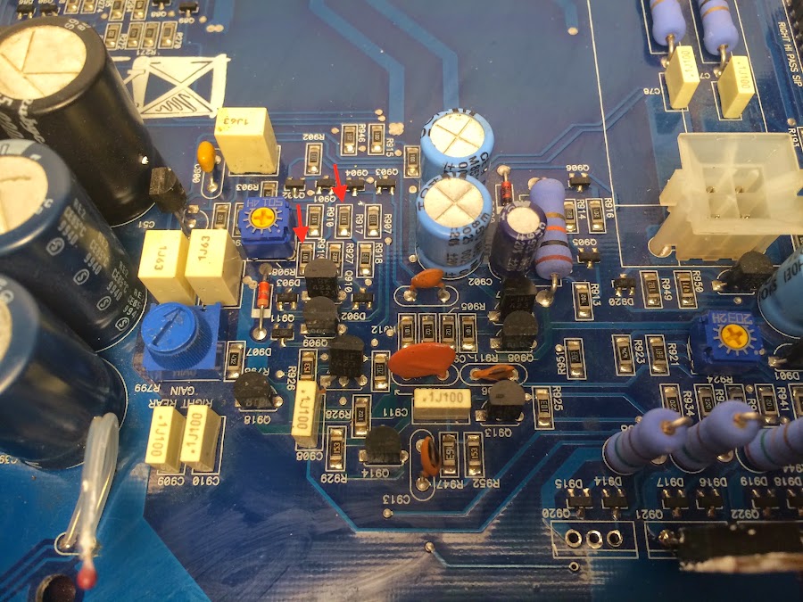
Okay, thank you to everyone who helped me here. I found it, and I fixed the issue! I had the two transistors swapped, stupidly enough. When I pulled the transistors from the donor board, I had gotten my sets wrong (when flipping it, I forgot to take into account where the transistors 'would' be and grabbed the wrong set). All channels are fine. Now, can someone tell me which pots are DC offset and which are DC bias? I ended up measuring the four pots (that would be where the one above is labelled '2032H' in each channel), and made them all even, and then I took the other 4 (labelled 5014H, but also on the same spot each channel) and moved them until my outputs all read >.01 mv DC output. I am assuming the first one I mentioned (2032H) is the bias, and the 5014H is the offset? Also, does anyone know what the DC bias is supposed to be for these? The right-hand side leg of the one I am assuming is bias reads I believe about 150mv DC for me. Thanks guys!
501 is DC offset. 203 is bias, according to my notes.
The offset isn't likely to hold well. With changes in temperature, the offset shifts. You can see this by monitoring the offset with the amp warm then blowing cool air over the channel being monitored. The offset will generally drift.
The offset isn't likely to hold well. With changes in temperature, the offset shifts. You can see this by monitoring the offset with the amp warm then blowing cool air over the channel being monitored. The offset will generally drift.
So just to double check, 501 mv for offset, 203 mv for bias? And my assumption for which controls what was correct? Also, where exactly should I take measurements, from the 'outgoing' leg of the pot? Why not set DC offset to zero, out of curiosity? Thanks for helping me learn!
Ohhhh okay duh! Thanks, that was a stupid lack of realization. I was wondering why I would not at least aim for 0v offset, but I couldn't think of what else the numbers could be. Thought it was going to be some electrical science response like "the heat changes the characteristics and when warm, where an amp spends most of its' time, the DC iffset would then be correct" or something. But I will do that.
Any clue what the DC bias is supposed to normally be? Or should I just try to make an 'educated guess' based on the spec sheet hold-open value of the transistors being run?
As always, thanks for your time. I'm glad to have this amp that I've loved for a good while, almost back and running!
Any clue what the DC bias is supposed to normally be? Or should I just try to make an 'educated guess' based on the spec sheet hold-open value of the transistors being run?
As always, thanks for your time. I'm glad to have this amp that I've loved for a good while, almost back and running!
I'd set it as shown in the following demo if you cannot find factory specs. All transistors must be tightly clamped to the heatsink before you attempt to adjust the bias.
http://www.bcae1.com/temp/ausettingbias.swf
http://www.bcae1.com/temp/ausettingbias.swf
- Status
- This old topic is closed. If you want to reopen this topic, contact a moderator using the "Report Post" button.
- Home
- General Interest
- Car Audio
- Xtant x604 Repair Help