It's a great start and you've done well to learn the software. 
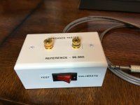
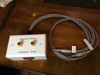
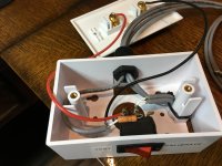
As mentioned above, you'll want the real driver impedance to make this accurate. You can build a rig to measure impedance with REW, or get a USB device made to do so. Then you're cooking!
I noticed that you did not attenuate the horn driver in your crossover. Don't you need to? A L-Pad there will also flatten the impedance curve seen by the crossover.
I do plan to keep the L-pad, but I want to measure it to see it's characteristics at minimum, center, and maximum so I can properly insert the resistances. I did try the CircuitBlocks L-pad, and it seemed to work fine, but I didn't know how closely it matched the L-pad I am using. I'd like to get this designed with the desired FR with the L-pad in the center position. It occurs to me that since I adjusted each driver for 75db for the REW testing, that's why they blend nicely without the L-pad. Back to the drawing board.It's a great start and you've done well to learn the software.
As mentioned above, you'll want the real driver impedance to make this accurate. You can build a rig to measure impedance with REW, or get a USB device made to do so. Then you're cooking!
I noticed that you did not attenuate the horn driver in your crossover. Don't you need to? A L-Pad there will also flatten the impedance curve seen by the crossover.
I'll search for the details on how to measure the impedances.
Thanks to everyone for the feedback - I'd like to try to get this as close to right as possible before I order parts.
OK, I found the information I need to measure the impedances. I assume it's OK to measure the drivers in their enclosure and not free-air? Seems like the enclosure could influence the readings - especially a ported enclosure where there is interaction at the tuned frequency?
OK, I guess I need to do more homework. I told XSim to use derived impedances for the zma file, but I guess that's not going to work.
(I assume you mean in Xsim3D?). The 'derived' refers only to the phase of the impedance curve. It derives the phase curve from the impedance magnitude (ohms) curve so without a realistic magnitude curve, "derived" won't do anything good.
But it looks like you've gotten a decent measuring rig set up for it, so get the right impedance curve before simulating.
And watch out for the L-Pad -- those aren't usually very great in terms of power handling (don't trust the spec!) and love to go intermittent. I'd avoid them altogether if I were you, you have stuff to measure with accurately so you don't really need the cheat.
...and I mean it's a good thing to measure with the enclosure influences
What microphone did you use ?
My question was about impedance testing and whether to test the driver in free-air, or installed in the enclosure you are designing the x-over for. I believe it should be done in the enclosure so that any influences it has on impedances will be measured. Hopefully someone will correct me if this is wrong.What microphone did you use ?
For my frequency response measurements I used a UMIK-1.
I am using XSim, not XSim3D. I didn't understand the function of the use derived data checkbox. Thanks for the comment about the L-pad, I will have to watch that and decide whether to keep it. To eliminate it, would I just substitute two fixed resistors in it's place to match the output level of the drivers?(I assume you mean in Xsim3D?). The 'derived' refers only to the phase of the impedance curve. It derives the phase curve from the impedance magnitude (ohms) curve so without a realistic magnitude curve, "derived" won't do anything good.
But it looks like you've gotten a decent measuring rig set up for it, so get the right impedance curve before simulating.
And watch out for the L-Pad -- those aren't usually very great in terms of power handling (don't trust the spec!) and love to go intermittent. I'd avoid them altogether if I were you, you have stuff to measure with accurately so you don't really need the cheat.
The rig looks cool.  Yes, measure the impedance of the drivers in the box. Since that's where they will be when you use them, that's where you want to measure them.
It seems that you've figured out how to use the L-Pad circuit, which is going to change the impedance curve and output of the. horn driver, so it needs to be in place a you work on the high pass section.
 Yes, measure the impedance of the drivers in the box. Since that's where they will be when you use them, that's where you want to measure them.
It seems that you've figured out how to use the L-Pad circuit, which is going to change the impedance curve and output of the. horn driver, so it needs to be in place a you work on the high pass section.
My question was about impedance testing and whether to test the driver in free-air, or installed in the enclosure you are designing the x-over for. I believe it should be done in the enclosure so that any influences it has on impedances will be measured. Hopefully someone will correct me if this is wrong.
For my frequency response measurements I used a UMIK-1.
Does UMIK-1 need a phantom power supply ?
No, it's a USB interface and comes with a calibration file. You can find them here - UMIK-1Does UMIK-1 need a phantom power supply ?
No, it's a USB interface and comes with a calibration file. You can find them here - UMIK-1
Thank you so much.
I will now start my DIY loudspeaker and need a mic to make measurements with arta.... this one seems very good for starters
You're welcome. It seems to be pretty well regarded. If you decide to try REW, there's a good support forum over at AVNirvana.Thank you so much.
I will now start my DIY loudspeaker and need a mic to make measurements with arta.... this one seems very good for starters
I found this thread on the Parts Express forum. It includes a response from BWaslo.I think the UMIK was developed by BWaslo. Is that right, Bill?
UMIK-1 and Omni mic - Are they the same? -
Techtalk Speaker Building, Audio, Video Discussion Forum
My sound card is not cooperating with port assignments and so I haven't been able to get good impedance readings yet. I ordered some 1/4" to 1/8" adapters so I can try with another sound card. Hopefully it works.The rig looks cool.Yes, measure the impedance of the drivers in the box. Since that's where they will be when you use them, that's where you want to measure them.
It seems that you've figured out how to use the L-Pad circuit, which is going to change the impedance curve and output of the. horn driver, so it needs to be in place a you work on the high pass section.
Once I master the capability to properly model these drivers and crossovers, I'm thinking seriously about designing proper fixed attenuation for the horn and eliminate the L-pad as BWaslo recommended. I feel sure I would never use that adjustment anyway.
How critical is the soundcard input impedance setting to the accuracy of the impedance tests? I know the docs say to enter 20KΩ if unknown. I'm not sure if this is valid measurement, but I have an LCRZ meter and I tested one of the input jacks (for Z) and it measured slightly over 60KΩ @ 100, 120, and 1KHz, and about 21KΩ @ 10KHz. Should I set REW for 20000, or something higher?
- Home
- Design & Build
- Software Tools
- XSim free crossover designer


