What is the "Auditory ERB" response used for?
It's a smoothing supposed to relate to the frequency resolution of human hearing. Between about1/3rd octave to 1/6th octave as I remember, depending where in the freq range. With the assumption that a graph can look like a speaker can sound! But the idea is that multple response bumps that fall within an "Equivalent Rectangular Bandwith" will sound the same as one bump over that bandwidth. Or that ripply variations in a response would sound about the same as that response shape that was smoothed witnin ERBs
Quick question for you...
Which is the best way to measure the drivers being used in XSim to visualize the XO regarding FR and phase?
A single position, at intended ear level for all measurements of the drivers?
Or
Each driver's measurement at the same distance, but with the mic moved vertically to be centered on the driver being measured?
Attachments
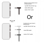
the top one, but if the tweeter isn't a ribbon or something super-fragile, don't use the 20uF cap (but keep the test level moderately low, as you'll want to anyway because the sound can be kind of annoying!).
Also, see Jeff Bagby's instruction on how to get the correct acoustic offset between drivers at IIS 7.5 Detailed Error - 404.0 - Not Found . The instructions are for use with PCD, but they work with Xsim, too. But that website seems to be down at the moment -- presumably Techtalk will get it sorted out soon...
--
To make things nice and confusing, the second (lower) method along with offset control is what you'd use with the "Xsim 3D beta" in 3D mode, though. I probably need to write up some brief instructions, but use the 3D thing for figuring out how to arrange the drivers, what kind of crossover topology might be needed, and a preview of how off-axis and boundary effects will change the response. Xsim3D will only give an estimate at that point, so don't build the actual crossover yet. When you decide on the drivers and baffle arrangement, then build the box and measure the drivers, as mounted in the box using the top method and without the 3D features of Xsim3D -- results from that, because they will contain all the baffle effects and actual off axis response will be nearly exact.
Last edited:
Here's a more general description of the procedure from my article in the old SpeakerBuilder magazine. It will work with any software that does 3D spatial positioning.
Finding Relative Acoustic Offsets Empricially
Dave
Finding Relative Acoustic Offsets Empricially
Dave
Xsim under Wine OSX
Hey Perceval. I know you mentioned getting Xsim to work well in Wine on the Mac, and some other people have mentioned it working no problems on Linux.
I can get the installer to run, but that's about it on OSX 10.13. After that it's gone. I have XQuatrz and Gecko, Hornresp runs just fine. Any thoughts or help?
I think I had the same "problem". After installing on the Mac you need to go to "wine" which looks like a windows directory structure and in these you will find "program files" and here there is XSIM....double click and it comes back again (instead of just the flash you see during installation)
I used the terminal window to drill down into the proper directory and got XSim to run with Wine. Seems to work just fine, expect for one thing: All pop-up dialog windows come up behind the main windows. Arrrgg. Sometimes I can drag them to the front, but usually the program is locked because there is no way to get to our interact with the pop-up.
Anyone fix that?
Anyone fix that?
XSim was working great, then, all the sudden, I can't open frd files...
I keep getting File Load Error, either with my own measured frd files with REW, or the files supplied by Dayton online.
Here's a look at my file from REW.
It was exporting fine from REW, and importing fine in XSim before, but for some reason, it just stopped working!
* Measurement data measured by REW V5.19 Beta 4
* Source: USB Audio CODEC, USB Audio CODEC, Left channel, volume: no control. Timing signal peak level -3.1 dBFS, measurement signal peak level -8.1 dBFS
* Format: 1M Log Swept Sine, 1 sweep at -23.0 dBFS Using an acoustic timing reference
* Dated: 20-Apr-2017 10:50:49 AM
* REW Settings:
* C-weighting compensation: Off
* Target level: 75.0 dB
* Note:
* Measurement: ahe15
* Smoothing: None
* Frequency Step: 0.3364563 Hz
* Start Frequency: 29.94461 Hz
*
* Freq(Hz) SPL(dB) Phase(degrees)
29.945 69.523 -170.472
30.281 69.338 -174.261
30.618 68.915 -175.682
30.954 68.536 -173.643
31.290 68.634 -168.874
31.627 69.410 -164.626
31.963 70.576 -163.753
32.300 71.714 -166.468
32.636 72.588 -171.558
32.973 73.129 -177.699
33.309 73.354 176.178
33.646 73.336 170.848
33.982 73.184 166.738
34.319 73.013 163.823
34.655 72.904 161.641
34.991 72.864 159.594
....
Is there a location where people upload their speaker measurements to? I'd like to try out some different speakers than I have, but there doesn't seem to be a lot out there?
Hi Jimbodiah,
I've been pushing for such a thing for years, but it's not as straightforward as it might seem. To be useful, measurements need to be well controlled (more so that most are done). Most important is the signal test level (sensitivity) -- you'd have to have a way to set the signal test level to a known value and the measurement sensitivity to keep things so they are comparable between different drivers (ideally: 2.83Vrms at 1m).
Almost as important is having a consistent delay plane (how far the mic is from the speaker, actually or effectively, as that dramatically affects the phase response) -- I'd push for that to always be delay adjusted in the data to correspond to an (imaginary) mic placement at the mounting surface of the driver on a baffle. But even that has problems if you are modeling for off-axis response, as the "actual" source of most drivers is somewhere behind the baffle, so when you look at the driver off-axis you also need to know where that 'fulcrum' point is (how far behind the baffle).
And on the subject of off-axis, doing that almost forces a different way of doing modeling than most of us have done with Xsim or PCD. If you measure your drivers on the final intended baffle with the mic in a fixed position and relative delay between the drivers managed in the data, your simulation result (for that microphone placement) will be virtually exact and match what you measure after the crossover is built. But if you have generic data (on a different baffle, like an infinite one), you need to add simulation of baffle effects like diffraction or baffle step to your sim. That's handled in some software (though not in Xsim, as of yet at least). But a subtle point is that such data will from on-axis but your mic and listening position can't be on-axis for all the drivers in a system (with a few exceptions like coaxials). So, then you need to have data for off-axis behavior in some form, and have the software account for that. That's where I was going with Xsim3D (the beta), when it dawned on me that the process for using something like that is quite different from getting real data on a real baffle at real angles and simulating from that. If you take care of baffle effects (using a simulator for that such as in VituixCAD or Jeff Bagby's) and assume you're designing for far enough away that off-axis isn't too crucial, you can get a good enough result to design with but you won't get exact results (if you're used to that).
My thoughts now are to use something like the 3D mode of Xsim3D just to get a feasibility model - place drivers to see how the spacings interact, add a baffle effect response for each (the "Acoustic Response FRD" file field) driver, and do a 'proposed' crossover just to make sure it all can work out well enough both on and off-axis. Then buy the drivers and build the actual box and THEN make actual measurements for doing the final design (using a non-3D mode).
It would be possible to get a pretty accurate design in a 3D mode using lots of software firepower (VituixCAD is targeting that approach I think), but that would also require extensive measured data for each driver, which is more than most DIYers are likely to really do -- not a lot of patience for doing full 3D measurements of drivers. It's hard enough to get people to keep SPL levels controlled, harder to get delays controlled, almost never done to have usable off-axis data for modeling.
For what it's worth, I tried to start a thing called "standardized FRD files" (originally defined for Dayton Audio when they started to post data on their drivers and wanted to make it more useful for customers). It was basically just an FRD file format but with the words "Standardized FRD file" on the very first line after some quote marks and some descriptive words. Also included was an "acoustic origin", which is the effective position of the measuring mic for phase delay. Probably should've had another field for the effective 0delay position where the sound appears to start (that could be figured maybe via comparing to Hilbert phase?). Here's what a header on a "Standardized FRD" file looks like:
"| "| "| Standardized FRD file, measured by OmniMic "146122014.omm" on 6/19/2014 by userID: BrMy
"| "| "| Equivalent to driven with 2.83V and measured at 1m
"| "| "| Acoustic origin is 165.7useconds behind the mounting plane.
"| "| "|
"| "| "| Equivalent to driven with 2.83V and measured at 1m
"| "| "| Acoustic origin is 165.7useconds behind the mounting plane.
"| "| "|
Hello,
Thank you for your reply.
I understand that standardziing test and making sure conditions for all of them are the same will be impossible if just anyone could send in a plot, but I think it could even work as just a reference library to test out some drivers in XSIM. The best way to make the plots is to test the units you actually own, but I don't yet have some of the units I want to try out, but would like to start tinkering with XSim")
Thank you for your reply.
I understand that standardziing test and making sure conditions for all of them are the same will be impossible if just anyone could send in a plot, but I think it could even work as just a reference library to test out some drivers in XSIM. The best way to make the plots is to test the units you actually own, but I don't yet have some of the units I want to try out, but would like to start tinkering with XSim
Then, you better use the info from the manufacturer, instead of somebody's enclosure, baffle and room design that will surely not be like yours.
There are programs that imports frd files from the graphics given by manufacturers, like FPTrace, SPL Trace, etc...
Here:
FPGraphTracer : fprawn labs
There are programs that imports frd files from the graphics given by manufacturers, like FPTrace, SPL Trace, etc...
Here:
FPGraphTracer : fprawn labs
Last edited:
Jimbodiah, for play, the Dayton drivers sold by Parts Express mostly all have .frd and .zma files available from their site. The FRD files are done as I described above (relative to 2.83Vrms drive, 1 m away, and delay plane set to the mounting baffle surface).
Hi-Fi Woofers, Subwoofers, Midranges & Tweeters in the Speaker Components Department at Parts Express | 13
Click on a driver of interest and on its web page under "Manuals and Resources" there will usually be a zipped file of ZMA and FRD, including some off-axis ones. These are all done on semi-infinite baffle (below 400Hz data is from near-field). So, if you include a baffle effect simulation and include that in the "acoustic effect frd" for each driver, you can get a reasonably accurate crossover design without buying anything yet.
- Home
- Design & Build
- Software Tools
- XSim free crossover designer