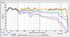
For reference, a screen shot of the horizontal K-402-MEH, measured outside on a stand quasi-anechoically, polar frequency response curves (0-90 degrees in 10 degree increments)--before I adjusted the crossover filter overlap to take out the relative null associated with the crossover frequency at 475 Hz:
Attachments
I had the fonts set on 125%. I returned them to 100%, and I can now see the horizontal scale arrows:

I keep the fonts at 125% due to my demastering over an HDMI bus to my TV and audio setup. The fonts are a little too small to see them at 100% from 12 feet viewing distance on a 65" screen...Thanks for the debugging.
Perhaps adding a little margin to the polar frequency response plot will alleviate this "feature"?
Chris
Give this a try:
http://libinst.com/junk/transfer/OmniMicInstall.exe
I set it so that form isn't "scaled". Didn't think that affected font, but maybe it does. I also moved the little arrows upward a bit.
http://libinst.com/junk/transfer/OmniMicInstall.exe
I set it so that form isn't "scaled". Didn't think that affected font, but maybe it does. I also moved the little arrows upward a bit.
I had the fonts set on 125%. I returned them to 100%, and I can now see the horizontal scale arrows: <snip>
In Windows, note that multiple video cards will cause all kinds of weirdness with scaling. Here's an example:
My laptop is 1920x1080. My "monitor" is a 55" UHD TV with a resolution of 3840x2160. I have two graphics cards: an Intel card built onto the system board, and a Nvidia card that's optional.
Without fail, my apps and fonts get wrecked when I switch from the laptop screen to the monitor screen. I wind up with fonts that are easily twice as big as they should be.
It's super annoying. I'm half tempted to go back to Windows 7.
I think the problem is you can't scale just the fonts without breaking some app's screen layout. Win10 either has removed the ability to do so or hidden so well I can't find it. But they do provide the ability to scale entire objects which works reasonably well so long as you have a high enough resolution and physically large enough screen. For my old eyes I just set the object scale factor to 2x and I can read even the small type on my 4K laptop screen and 3840x ultrawide monitor.
I'm using Windows 7 presently-so the implied remedy is also having issues.
Note that the updated version of OmniMic that Bill posted above also has the same issue with the horizontal scale icons disappearing. I got the workaround - just change the fonts back to 100%, then log off and then log back on. Voila! Problem worked around. No biggie. The price is right, too.
Thanks again, Bill. You've done a lot for the DIY community--yet again.
Chris
So, Bill, quick question. In XSin (hah!) I used the driver acoustic offsets to determine phase matching. Conventionally, I set the tweeter to zero, and the woofer offset based on traditional interferometry, measuring off the tweeter axis.
I notice in XSim 3D everything is measured from the center of the baffle.
So how do I go from one to the other?
Best,
E
I notice in XSim 3D everything is measured from the center of the baffle.
So how do I go from one to the other?
Best,
E
Uh, yeah. Good question (and a bit of a complication). Basically, there would be 2 ways to use Xsim for a speaker crossover (and I had done most of the programming for XSim before realizing this).
The "original" way was to make all your measurements with the drivers in the baffle and the mic at a good approximation of the on-axis listening point (though usually closer, to get more 'anechoic' time from windowing). Do the 3-measurement method (tweeter, woofer, then both playing together). Adjust the delay on one or the other so that a sim of "both playing together" matches the measured "both playing". Then use that delay to design the crossover. This gives an essentially perfect simulation of the crossover response shape for that situation. It's generally a good idea to go with multiple microphone positions around the baffle, match for delay, and then simulate the crossover at those positions to get a view of of-axis response. "Off-Axis", in this case, being relative the the BAFFLE.
But with the 3D features (which can be turned off. so the previous method still works), it is assumed that an "off-axis" measurement is relative to each DRIVER, like you pointed out. That could be a nice development arrangement as it could lead to getting a library of drivers, measured on an infinite baffle, all set to go to play 'what-if' with. But the complications: first you have to (at least with Omnimic or anything that can't do a time-locked non-drifting true delay measurement) still do a three- measurement thing with the mic in the same place for both drivers to get the delays set right, then measure drivers again on axis (and maybe at a set of off-axis) to get their off-axis responses. If you use the "piston model' thing, you can probably get away with just an on-axis measurement and the piston off-axis approximation won't be too bad (but of course not exact). I should note that Dayton Audio provides FRD file sets for most of its drivers, measured on an almost-infinite baffle and with time of flight delay already adjusted so they all use the same reference, so you could use those this way without doing your own measurements, at least for a simulation of feasibility. (But note, Dayton only provides off-axis out to 45 degrees, so any sims involving sound going off at angles beyond that will be extrapolated, not interpolated, so accuracy can be pretty poor when very far off).
But a maybe bigger source of inexactness is that XSim still doesn't model any baffle diffraction or baffle step effects, so while it will get delays between driver right for their positions (and reflections off the floor, ceiling, etc), it will still simulate as if the drivers were on an infinite baffle. At present, you'd have use some of Charlie Lamb's or Jeff Bagby'so or other's tools to get baffle effects into the measurements (as an "Acoustic Efffects" FRD file).
I see that kimmosto's VituixCAD does simulate baffle effects at least to some extent and provides off-axis simulation, but I don't know offhand what the measurement requirements are for it.... I should probably look into it sometime. It doesn't appear to support free-form (weird) crossover circuit arrangements but it does seem to have a lot of subnetworks to choose from if you're going with straightforward arrangements. VirtuixCAD kind of lowered my level of inspiration to do much more to XSim, though Steve Bolser has given me some algorithms for baffle effect simulation I do plan to add at some point, maybe next winter. Or maybe it would be easier to send kimmosto my code for the fast circuit matrix solver to add to Vituixcad?
The "original" way was to make all your measurements with the drivers in the baffle and the mic at a good approximation of the on-axis listening point (though usually closer, to get more 'anechoic' time from windowing).
With HolmImpulse one gets the exact inter-driver delay automatically if the time base is locked. This is why I chose to use it. I get pretty much perfect polar sums with just the two driver measurements.
I am leery of the "rigid disk" approach to polar effects. At higher frequencies I would not expect this to be very accurate and for a dome tweeter or a waveguide it is not even close to being accurate.
Holm will only get the base really locked when used with certain sound cards. A surprising number of modern soundcards use a different crystal reference for recording and playing and from the small ppm difference those won't sync but will drift in and out. The best sometimes are the cheapest soundcards (except the USB soundcards that use TI USB audio chips, such as the Behnrengers -- for some inexplicable reason, one function uses an onboard crystal and the other is phase locked to the USB 1kHz clock). That's one of the reasons I got away from trying to make a general soundcard measurement system, it got really old playing "what's the matter with this one" on soundcard functions. The other reasons are ground loops making ground loop noise and buzzing with external audio equipment, based largely on lucky combinations; and of course the goofy Windows soundcard driver situatiion. But if you get one that works well, and don't change operating systems to something unsupported, the synchronously locked setups work very nicely.
Granted the disk approximation won't be right at all for waveguides, but XSim is a crossover program -- the approximation for circular tweeters at likely crossover frequencies isn't going to be terrible.
Granted the disk approximation won't be right at all for waveguides, but XSim is a crossover program -- the approximation for circular tweeters at likely crossover frequencies isn't going to be terrible.
I do tend to use the low end sound cards as they work just fine. Sometimes Holm does jump synch and that forces you to "start all over" - a real PITA. But 80% of the time it works fine with my cheap Behringer USB card. I have a bad habit of blowing up sound cards so I have to stick with the cheap ones. Anyways the data from even the cheapest sound card is an order of magnitude better than the simulation results.
I guess that my expectations for crossover simulations must be higher than yours as I just cannot see anything with a waveguide - large or small - being even remotely approximated by a rigid disk. It's the polar response at crossover that is critical and it takes a very high level of accuracy to get this right globally. For one speaker it is the low-end, but for the other it is at the upper end of its bandwidth. Small errors can be big errors in the sims. I have done polar response simulations and matching them to measurements for decades and I think that you are kidding yourself to think that a rigid disk approximation is going to be "OK".
I guess that my expectations for crossover simulations must be higher than yours as I just cannot see anything with a waveguide - large or small - being even remotely approximated by a rigid disk. It's the polar response at crossover that is critical and it takes a very high level of accuracy to get this right globally. For one speaker it is the low-end, but for the other it is at the upper end of its bandwidth. Small errors can be big errors in the sims. I have done polar response simulations and matching them to measurements for decades and I think that you are kidding yourself to think that a rigid disk approximation is going to be "OK".
I don't know offhand what the measurement requirements are for it.... I should probably look into it sometime.
See the latest Measurement Preparations.pdf. Refresh if date is older than 10.4.2018.
My policy is quite strict: dual or semi-dual channel measurement mode (or constant latency gear) is required to lock timing and phase information to rotation center of each driver while off-axis measurements. That point is virtual center point of the driver. Locations relative to perpendicular point of design axis on tweeters baffle are entered to the simulator: VituixCAD, LspCAD 5-6 or whatever supporting 3D driver locations. No need to detect differences in acoustic centers which could be slow PITA with off-axis responses. Also minimum phase extraction is forbidden (with some exeptions) because it ruins previous timing reference system and disables capturing of possible non-minimum phase features of the drivers.
Or maybe it would be easier to send kimmosto my code for the fast circuit matrix solver to add to Vituixcad?
That would be very generous, but I'm afraid that conversion to free-form schema could be too massive job (compared to my current motivation). Foundation of crossover calculation and schema graphics is not so excellent because VituixCAD is my first C# project developed from tiny study to elephant without initial master plan for classes etc. But I promise to look carefully and consider seriously if you decide to sent source code. I already have C# spice source but threshold to make fresh start with it is quite high.
Is that C# spice code open source? My program, WinPCD, is also C# sharp using a couple of open source packages, primarily for the graphs. If the spice code is open source I'd be interested in seeing if it is significantly faster than my code for matrix calculations.Foundation of crossover calculation and schema graphics is not so excellent because VituixCAD is my first C# project developed from tiny study to elephant without initial master plan for classes etc. But I promise to look carefully and consider seriously if you decide to sent source code. I already have C# spice source but threshold to make fresh start with it is quite high.
Are you aware of any open source for free-form circuit element placement and matrix setup? That is what limited me when I started. My program was also my first work in C#.
Dave
Is that C# spice code open source?
Here is spice with C#.
GitHub - SpiceSharp/SpiceSharp: A Spice-based circuit simulator written in C#. It uses Math.NET to solve matrix equations.
This is using math.net for matrix routines as far as I remember.
Are you aware of any open source for free-form circuit element placement and matrix setup?
LiveSPICE has free-form schema editor, spice and emulator with convolver I guess. Some math routines are not included in that package.
GitHub - dsharlet/LiveSPICE: Real time SPICE simulation for audio signals
LiveSPICE
Another open source circuit simulator, but with cpp
Quite Universal Circuit Simulator
Quite Universal Circuit Simulator
Unfortunately,if we enter the relative position point to the VituixCAD,the phase response of the individual driver changes the final on-axis FR will alter due to such a minor action.I have a copy of leap crossover software and I choose the SPL phase at the microphone instead of at the voice coil,no matter what the position point I enter the final on-axial FR will not be altered.It's a processing system different from VituixCAD.However,I don't dare to find the acoustical center of drivers because it's hard to identify the accurate value.Locations relative to perpendicular point of design axis on tweeters baffle are entered to the simulator: VituixCAD, LspCAD 5-6 or whatever supporting 3D driver locations.

Back to VituixCAD,I enter 0 position information after I get the relative phase of woofer and tweeter then I did get the fine result identical to on-site FR but no polar map is simulated.Maybe someday I'll perform the test and try it,thanks!
Last edited:
Unfortunately,if we enter the relative position point to the VituixCAD,the phase response of the individual driver changes the final on-axis FR will alter due to such a minor action.
There is nothing unfortunate. Phase response must change when driver is moved so that distance from microphone to driver changes. Reference distance is from mic to origin (0,0,0) on the baffle.
If you get different result compared to measured sum, the reason is timing errors/differences in frequency responses of individual drivers.
VituixCAD will not interpolate frequency responses between measured angles. That is one error source which motivates to measure off-axis response with steps of 10 deg or less.
That is one error source which motivates to measure off-axis response with steps of 10 deg or less.
This is exactly the source of error that prompted me to develop my modal approach to measurements. It does not have this error even with a smaller number of measurement points.
- Status
- This old topic is closed. If you want to reopen this topic, contact a moderator using the "Report Post" button.
- Home
- Design & Build
- Software Tools
- Xsim-3D development... I could use some math help