Hi stellarelephant. I see you are doing some good research on caps, and I would like to hear your findings specifically relating to this amp. A year ago I was also fascinated by all the different caps and how they possibly affect final sound. A lot has been said about this topic already.
You might find this interesting regarding PPS caps – Wiki says: “The temperature dependence of the capacitance of PPS film capacitors over the entire temperature range is very small (± 1.5%) compared with other film capacitors. Also the frequency dependence in the range from 100 Hz to 100 kHz of the capacitance of the PPS film capacitors is ± 0.5%, very low compared with other film capacitors. The dissipation factor of PPS film capacitors is quite small, and the temperature and frequency dependence of the dissipation factor over a wide range is very stable. Only at temperatures above 100 °C does the dissipation factor increase to larger values. The dielectric absorption performance is excellent, behind only PTFE and PS dielectric capacitors.
Polyphenylene sulfide film capacitors are well-suited for applications in frequency-determining circuits and for high-temperature applications. Because of their good electrical properties, PPS film capacitors are an ideal replacement for polycarbonate film capacitors, whose production since 2000 has been largely discontinued.”
So, PPS caps are replacing Polycarbonate caps – but I found this interesting post on the ACA amp thread regarding the input caps, posted by the mighty Zen Mod: “so , 20uF solid cap , bypassed with 0u47 to 1uF, as I said - my fave are Icar motor run , bypassed with MKC (polycarbonat)”
No way you can use a motor run cap here, but the PPS might hold good possibilities although it looks like they mostly come in SMD.
I have two ginormous 50uF motor run caps sloshing with oil inside. Brand new. I just might connect them to the big desktop version of his amp and take a listen. 50uF is enough for 250ohm cans all by themself to reach decent bass levels.
This PPS cap business is really interesting though.
This PPS cap business is really interesting though.
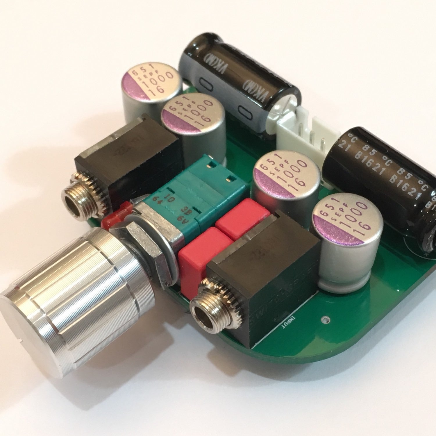
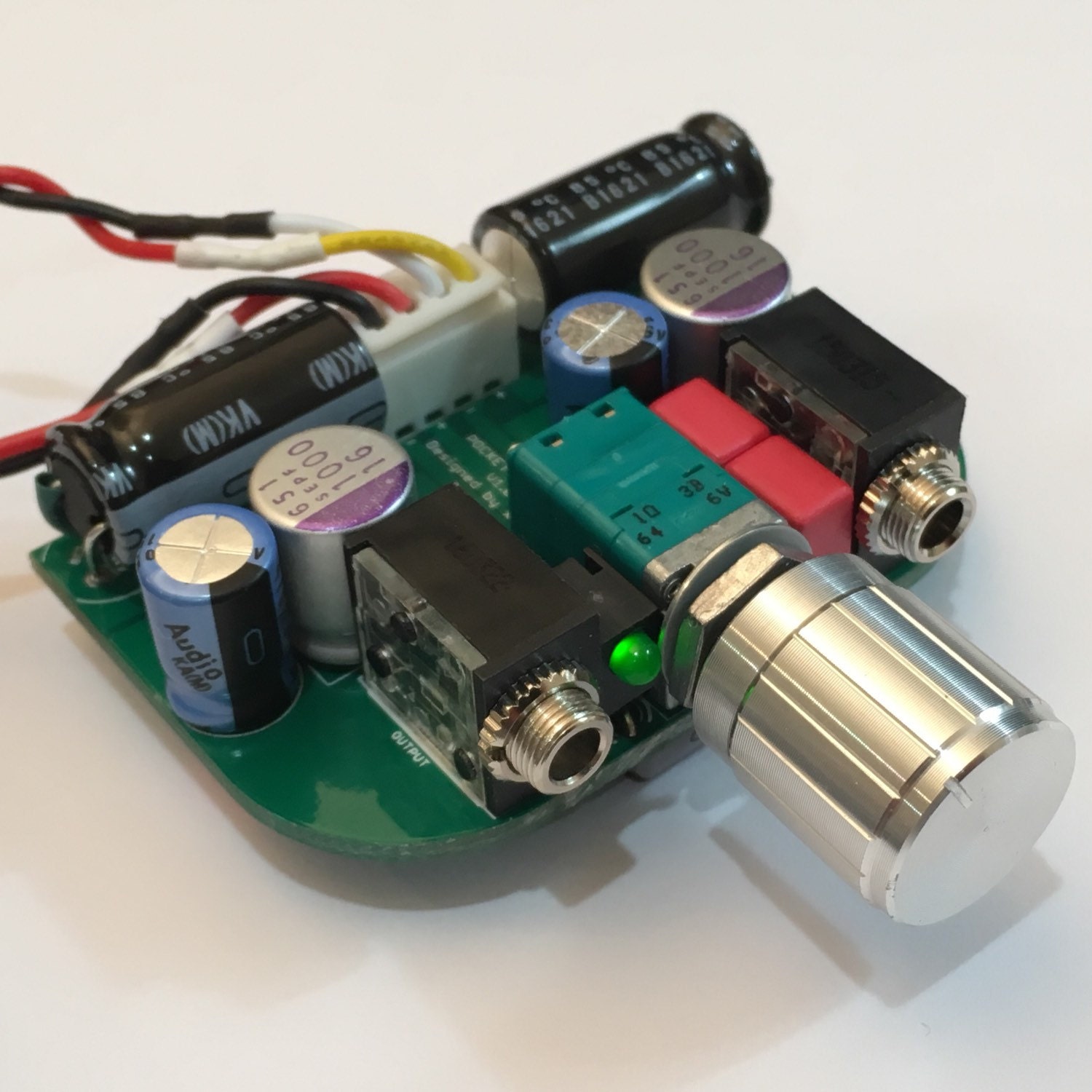
Testing the desktop version of this amp with a 19v laptop SMPS feeding a Linear Technologies LT1963A low dropout low noise regulator set at 18v. Amp runs at 113mA bias through IRF610 MOSFETs. Tested with 33ohm load parallel with 250ohm headphones in order to listen to effect of lowninpedanxe loading. Sound is very nice and bass is very good. No audible hum or noise at all. Amp is fitted with two massive 10000uF 25v rail caps and also using two 1000uF 16v oscons:
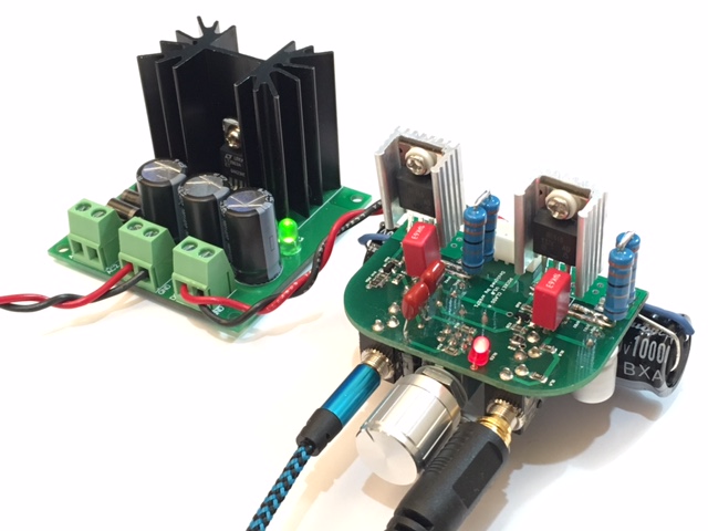
Attachments
Last edited:
Hi stellarelephant. I see you are doing some good research on caps, and I would like to hear your findings specifically relating to this amp. A year ago I was also fascinated by all the different caps and how they possibly affect final sound. A lot has been said about this topic already.
You might find this interesting regarding PPS caps – Wiki says: “The temperature dependence of the capacitance of PPS film capacitors over the entire temperature range is very small (± 1.5%) compared with other film capacitors. Also the frequency dependence in the range from 100 Hz to 100 kHz of the capacitance of the PPS film capacitors is ± 0.5%, very low compared with other film capacitors. The dissipation factor of PPS film capacitors is quite small, and the temperature and frequency dependence of the dissipation factor over a wide range is very stable. Only at temperatures above 100 °C does the dissipation factor increase to larger values. The dielectric absorption performance is excellent, behind only PTFE and PS dielectric capacitors.
Polyphenylene sulfide film capacitors are well-suited for applications in frequency-determining circuits and for high-temperature applications. Because of their good electrical properties, PPS film capacitors are an ideal replacement for polycarbonate film capacitors, whose production since 2000 has been largely discontinued.”
So, PPS caps are replacing Polycarbonate caps – but I found this interesting post on the ACA amp thread regarding the input caps, posted by the mighty Zen Mod: “so , 20uF solid cap , bypassed with 0u47 to 1uF, as I said - my fave are Icar motor run , bypassed with MKC (polycarbonat)”
No way you can use a motor run cap here, but the PPS might hold good possibilities although it looks like they mostly come in SMD.
Thanks for sharing. Not the first time I've seen PPS touted as the successor of polycarbonate. PPS has low dielectric absorption, which Cyril Bateman maintained was the most important spec that correlates with low distortion. Plus there's the high temp stability benefit you mentioned. The only suitable PPS caps I found on Mouser are Kemet SMR. The datasheet boasts "excellent sound quality in audio applications". I don't know much about dissipation factor, or how important it is to audio, but in that category they seem to be outclassed by WIMA MKS. (Just comparing data sheet specs.) But they win in the dielectric absorption category and have been praised for linearity, so I think they have good potential. I'm looking forward to tying them for myself!
Here's the 1uF SMR. It is 7.2x7.2x13mm with 5mm lead spacing.
http://www.mouser.com/ProductDetail...=sGAEpiMZZMvJkDqKJH80dJrqmmmllbO/1e2hYXXKQKk=
I thought I had a suitable 2.2uF in my cart also, but now I realize it has 15mm lead spacing...
http://www.mouser.com/ProductDetail...=sGAEpiMZZMvJkDqKJH80dJrqmmmllbO/1e2hYXXKQKk=
I thought I had a suitable 2.2uF in my cart also, but now I realize it has 15mm lead spacing...
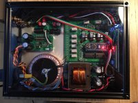
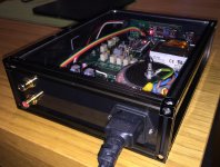
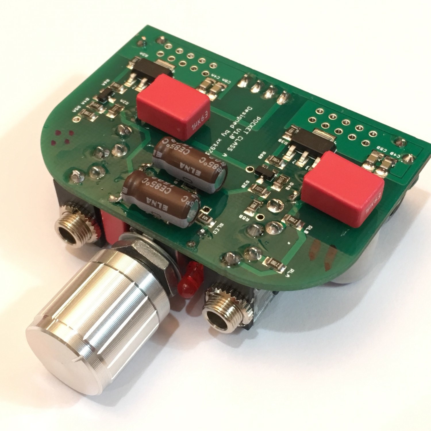
Here's my version of the xrk971's Pocket Class A headamp as a desktop version.
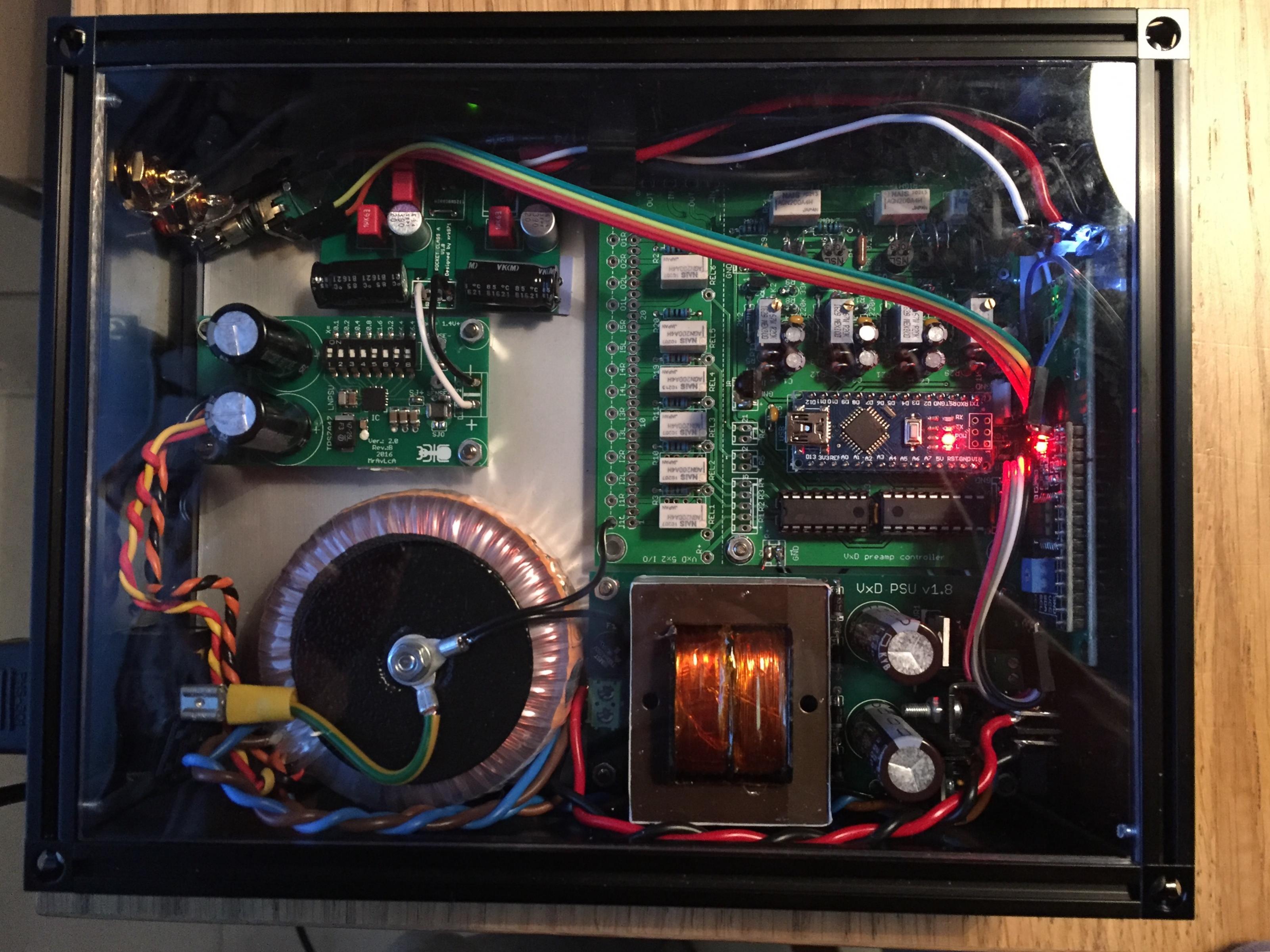
Most of the case is filled up with LDR volume controller and it's power supply. The headamp itself is powered via 30 VA 230/2x15V toroid and user Mravlca's TPS7A4700 LDO board. Voltage is set to 16 V.
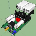
FETs are matched by X himself and the rail caps are 2200 uF/16 V. Otherwise it's a stock build and the bias is running at 57 mA in both channels. The FETs are connected to aluminum bottom plate via silicone pads. I still need to make some kind of aluminum bar on top of the amp board to squeeze it tighter to the base plate with M3 bolts and nuts.
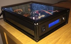
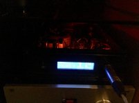
I propably will make new version of the face plate by using clear plexi glass and replace the power switch with rotary encoder. Now I have only remote control.
The sound is sweet, though I'm poor at describing the details. Well worth the effort!
Most of the case is filled up with LDR volume controller and it's power supply. The headamp itself is powered via 30 VA 230/2x15V toroid and user Mravlca's TPS7A4700 LDO board. Voltage is set to 16 V.
FETs are matched by X himself and the rail caps are 2200 uF/16 V. Otherwise it's a stock build and the bias is running at 57 mA in both channels. The FETs are connected to aluminum bottom plate via silicone pads. I still need to make some kind of aluminum bar on top of the amp board to squeeze it tighter to the base plate with M3 bolts and nuts.
I propably will make new version of the face plate by using clear plexi glass and replace the power switch with rotary encoder. Now I have only remote control.
The sound is sweet, though I'm poor at describing the details. Well worth the effort!
Attachments
Morde,
That looks absolutely fabulous. Nice work! Amazing how little the amp itself takes up! I was looking at a similar TPSA power supply regulator myself. How do you like it? Specs are 4uV noise and -80dB PSRR at 100Hz. Very nice. If desktop use and fitted with silicone heatsink - you can boost PSU to 19v if you change our those 16v rated 2200uF caps for 25v ones. The 19v PSU should push bias up to about 75mA to 80mA. Total dissipation will be circa 3.2W. But dynamics will get a big boost.
That looks absolutely fabulous. Nice work! Amazing how little the amp itself takes up! I was looking at a similar TPSA power supply regulator myself. How do you like it? Specs are 4uV noise and -80dB PSRR at 100Hz. Very nice. If desktop use and fitted with silicone heatsink - you can boost PSU to 19v if you change our those 16v rated 2200uF caps for 25v ones. The 19v PSU should push bias up to about 75mA to 80mA. Total dissipation will be circa 3.2W. But dynamics will get a big boost.
FETs are matched by X himself and the rail caps are 2200 uF/16 V. Otherwise it's a stock build and the bias is running at 57 mA in both channels.
It's nice to see confirmation that my hand-matched FETs are really matched when you build the amp. 57mA is a great sweet spot as bias current settings go. At this setting you are getting classic -66dB H2 and H3 between -12dB to -20dB below H2, not much else in higher orders, and THD of about 0.05%.
@xrk971,
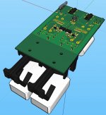
no modification since last post? Then I´ll start soon with a PCB: first, I´ve to finish my 12S LiPo BATT-PACK (standard components and some micro software, perhaps an display; charging with +5VDC wall-cube). Will work fine with your headphone amplifiers.
JP
no modification since last post? Then I´ll start soon with a PCB: first, I´ve to finish my 12S LiPo BATT-PACK (standard components and some micro software, perhaps an display; charging with +5VDC wall-cube). Will work fine with your headphone amplifiers.
JP
Attachments
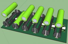
... waiting for test results IRF610 version (TKD potentiometer, Mundorf capacitors, PANASONIC ERA-6 resistors, WIMA, PANASONIC filtering, Soshine LiPo)...
JP
JPS64,
It's cool that you are designing your own board following my circuit design and basic layout. Can I ask why you don't just use the GB PCB that is already made and proven? If you want to make your own board, that's fine as this is DIY - but but please start your own thread as this thread is for this particular design and layout. I don't want multiple designs beyond current one to be in this thread as it is confusing to members. Thanks.
X
X: With the 270 ohm RLs, do they serve a purpose other than acting as a dummy load for testing like you mentioned somewhere early on in the thread? Should I just omit them when building it?
as a side note, RS components apparently had their stock levels wrong and didn't have any 1K SMD on hand...if it doesn't arrive soon I'm probably gonna use regular 1/8W resistors for the 1K ones ... lol
as a side note, RS components apparently had their stock levels wrong and didn't have any 1K SMD on hand...if it doesn't arrive soon I'm probably gonna use regular 1/8W resistors for the 1K ones ... lol
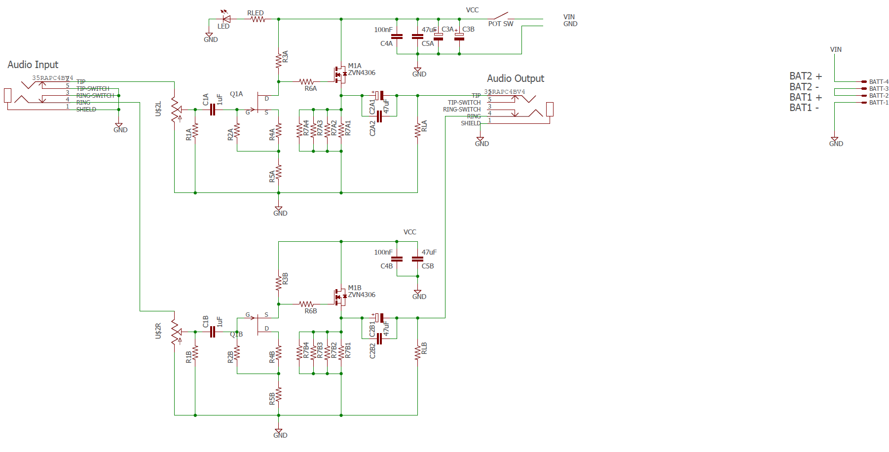
Thanks to BDHM for revising the schematic to be easier to use with designations A and B for left and right and paralleled parts with sub-numbers. Below are the new schematic, board silkscreens on topside (through hole) and bottomside (SMT) so you can see where everything goes.
Schematic:
Top side Layout Silkscreen:
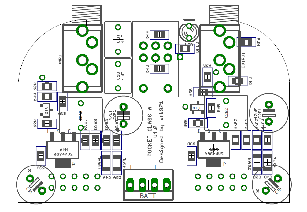
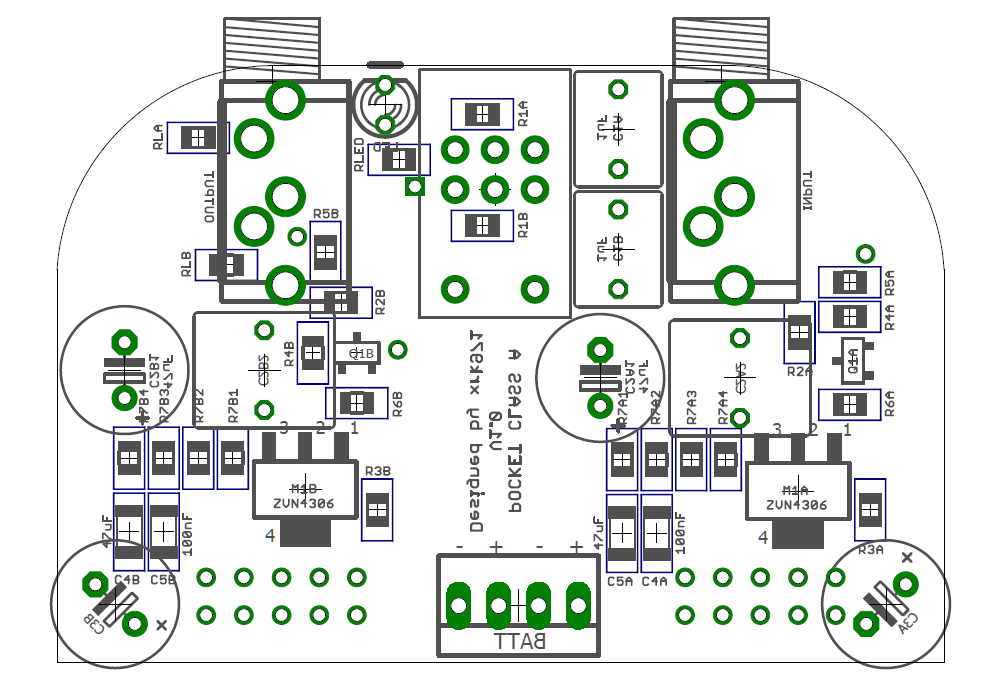
Bottom side Layout Silkscreen (note that 100nF C4A and C4B are mislabled 47uF - need to rework this before sending to fab):
BOM:
Code:All resistors 0805 package, metal thin film, 1% on specified parts, else 5%. Yageo 1% 0805 SMT from Digikey are $0.77 for 100 R1 100k (5%) R2 47k (1%) R3 1k (1%) R4 33R (1%) R5 270R (1%) R6 47R (5%) R7_1 470R (1%) R7_2 470R (1%) R7_3 470R (1%) R7_4 470R (1%) RL 270R (5%) User select (optional, use for higher current draw on amp) RLED 15k (5%) Current limit for LED, 15k or value according to supply voltage C1 Input cap 5mm pitch up to 5.5mm wide (Wima 2.2uF MKS2B042201F00JSSD) C2_1 Output cap 3.5mm pitch, 8 dia (390uF 20v Panasonic OSCON 20SEPF390M) C2_2 Output cap 5mm pitch, up to 9mm wide (Wima 1uF MKS2C041001F00KSSD) C3 Rail cap 100uF 3.5mm pitch, diameter whatever you can fit in the tin (100uF 20v Panasonic OSCON 20SEP100MX) C4 Rail cap 100nF 1206 package (50v X7R) C5 Additional 100nF rail cap 1206 package (50v X7R) Q1 BF862 (771-BF862-T/R) M1 ZVN4306GTA Switchcraft 3.5mm stereo jacks x2 (35RAPC4BV4) Alps 10kOhm stereo pot with power switch (RK0971221Z05) 3mm round LED (red or green) 4-pin 2.54mm pitch power connector (see post #44)
Hi all, I am new to DIYA and am very excited to begin building this uber pocket amp!
I only see the diagram of the top side of PCB, can someone point me to the SMT side of PCB so I know how to populate it correctly?
thanks!
Edit: ok i get it, if the part label is legible and not reversed then that is the part for that side...!!!
Last edited:
- Home
- Group Buys
- xrk971 Pocket Class A Headamp GB