Raptor,Note that on the Cap Mx, you're going to want to use a 47uF 25V cap instead of the 100uF 16V... until they make 100uF 25V in 1210 size
Thanks for sharing the files and explanation! Is there enough vertical room in the tin to stack two 47uF 25V caps on top of each other (in parallel)?
....
Hi X,That looks more like a general purpose lab bench supply vs a low noise/low ripple supply that is needed for an amp like the PCA.
Glad I didn't buy it yet! The description says "The ripple & noise is very low at <30 mVp-p or <3mVrms." What specs are adequate in your opinion?
You want no more 40uV. On a SE Class A amp, the ripple in the PSU rail is directly translated to hum as the amp has no PSRR to speak of. It relies on a quiet steady flow through its Class A MOSFET. Any sound we get is result of modulation of that Class A current flow. I like to see PSU's with -110dB or less ripple or circa 1uV ripple/noise.
Yes, it required a CRCRCRC to remove a broadband white noise hump from the DC step up that was present from 30Hz to 1kHz at about -80dB. With the filter it was flat and quiet at -126dB just like a battery. Like I said though, you really can't hear anything at -80dB but it bothered me because I could see it in the FFT. Although RaptorL has a cap Mx after the MT3608 so that my clean up quite a bit of it.
Raptor,
Thanks for sharing the files and explanation! Is there enough vertical room in the tin to stack two 47uF 25V caps on top of each other (in parallel)?
Oh, yes there should be if you don't put a heatsink on the MOSFET. However this would definitely make the board very lopsided (more so than it is already) and you'll have to find a clever way to mount it. Maybe little squares of double stick on top of the diode until it's level?
Alternatively, you could just solder it to the side of the one that's there. That would just make it wider, not taller.
")
X, I was thinking that Raptor had tried your exact recommended DIY LiPo setup, and still experienced the turn-on issues with it. After backreading, I see that Raptor skipped the CRCRCRC. So either method will work then?
Roughly speaking, how should the cap multiplier compare to the CRCRCRC in terms of battery life and heat dissipation. Which has better noise rejection? Obviously the cap mx wins for size! Sorry, I lack the technical prowess to draw my own conclusions here.
Also reading back through the Complete PCB/Amp thread on Head-Fi, I see that David Baldock has discovered a 18V Li-Ion pack that could possibly negate the need for either filter, unless of course the thing has a step-up inside it. He was having trouble getting one shipped here from China due to battery regulations, though.
Hmmm... At least I know that I want the USB load-sharing board either way! Oh yeah, just realized that a step-up will be required to run directly off USB.
Last edited:
I had to use a very wasteful 4.7R resistor between the DC step up and the CRCRCRC in order to slow down the in-rush. It generated heat - probably more so than a cap Mx. The Cap Mx, with ZVN4306 has about 2.7v drop across it. So power dissipated is circa 120mA x 2.7v or 324mW. I forget what the voltage drop across the 4.7R was but might be about same ballpark or maybe 500mW. The Cap Mx filters ripple very well so if you plug the USB into a walljack while listening, it will reduce hum.
Nice. Looks like I'm going to be using both of your boards then, Raptor. I would imagine that the amount of hum coming in via USB is quite dependent on the source... a computer USB port (assuming the computer has a good quality SMPS) ought to be much cleaner than the average wall wart USB charger. Good to know that a cap mx filters well.
xrk971 Pocket Class A Headamp
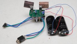
So here is my rough build on the PCA on steroids. Waiting for power supply bits. IFR610 doing the heavy lifting running 119ma bias with Similic 10uf on the inputs and 3300uf Pany FR on the outputs. 15000uf caps on the power supply lines from Apex Jr. one of the vendors on DIY. Currently running a lab supply until the other PS bits arrive.
I also have a battery only PCA and have been going back and forth listening to both playing the same songs. Source is a FIFO X3 playing FLACs and the cans are Thinksound OB-2.
To my old ears you would not be dissapointed listening through either version of the PCA. The PCA on steriods has a little more bottom end and to me seems a bit more forward. My plan is to turn the super PCA into both a headphone and line preamp. Something small, yet sounds very good.
I have several other DIY headphone amps and this is right up there. Just plan fun to build them.
Thanks X, keep it up.
Attachments
Nice. Looks like I'm going to be using both of your boards then, Raptor. I would imagine that the amount of hum coming in via USB is quite dependent on the source... a computer USB port (assuming the computer has a good quality SMPS) ought to be much cleaner than the average wall wart USB charger. Good to know that a cap mx filters well.
You might be surprised. Even with a good power supply there can be significant digital noise on the USB ports from various things after the supply or in the same case. I know powering it from my laptop generates no him but there is digital noise when the mouse is moved... Weird but not unexpected since the mouse is on the USB bus as well. This is with 2000uF Panasonic FR's and the cap multiplier board (probably part of a weird ground loop situation between USB audio and USB power on the PCA that the filter is incapable of fixing). Using a separate supply or batteries is dead silent.
Last edited:
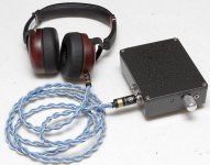
Speaking of journeys... I've finally got a finished and fully-functional USB/LIPO PCA!
This one features a single LIPO cell with micro-USB for charging and a load sharing board. This ensures that the battery is disconnected from the load and only charged when USB power is applied, while allowing the USB supply to also power the amplifier.
Link to the load sharing circuit - credit to Zak's Blog.
The 4.2-3.5V from the LIPO goes through a cheap, yet good, MT3608 boost converter module and then to the board. After the switch, the trace was cut and a capacitance multiplier circuit was inserted before the capacitors to give the circuit a needed soft-start functionality. (Thank you XRK for the recommendation, it works perfectly - even with a 47uF cap instead of 100uF!)
Without this final capacitance multiplier modification, the massive inrush of the large, low-ESR Panasonic FR's would trigger the over-current protection in the LIPO cell and some (but not all) 5V USB supplies. Here's a picture of the final incarnation:
This actually looks like the "ideal" build - external power source or batteries all in one and done neatly with a convenient USB connection!
But....I'm not too clear on what a capacitance multiplier is/does - could someone enlighten me?
Any schematics of your particular capacitance multiplier, raptor?
But....I'm not too clear on what a capacitance multiplier is/does - could someone enlighten me?
Any schematics of your particular capacitance multiplier, raptor?
The cap multiplier was my suggestion to use as a soft-start mechanism to slowly ramp up the current from the DC step up to the cap bank to prevent the batteries or the DC step up to go into auto shutdown due to the large in-rush current upon power-on.
It also provides a nice ripple reduction as a side benefit. I used these between all my DC step ups and cap banks on my amps. Most of the time, a much bigger IRFP240 or IRF610 is used.
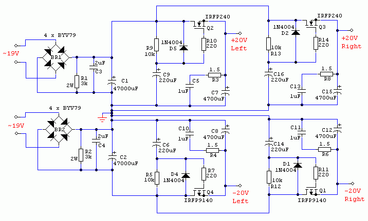
Cap Mx circuit is from this thread:
Juma's Easy-Peasy Capacitance Multiplier
Just use the top right quadrant with IRFP240. You don't need the 4700uF (the amp's own rail cap provides that). The 220uF cap can be replaced with 47uF cap and it all works fine still. YThe IRFP240 can be replaced with almost any N-channel power MOSFET suited for your currrent load and voltages. Since the ZVN4306GTA is what we already use and have on hand, RaptorL used that and it works well.
You might be surprised. Even with a good power supply there can be significant digital noise on the USB ports from various things after the supply or in the same case. I know powering it from my laptop generates no him but there is digital noise when the mouse is moved... Weird but not unexpected since the mouse is on the USB bus as well. This is with 2000uF Panasonic FR's and the cap multiplier board (probably part of a weird ground loop situation between USB audio and USB power on the PCA that the filter is incapable of fixing). Using a separate supply or batteries is dead silent.
If you can stomach spending $50 on a wall wart, iFi audio makes this little 5V switcher that manages 1uV noise rather cleverly via active noise cancellation. (Now if we could just reverse engineer that circuit...) Comes with a micro USB tip.
For $23 you can use one of these for 0.8uV noise at selectable voltages to 15v and 500mA.
LT3045-S Ultralow-noise (0.8mVrms) LDO linear regulator 0V-15V - 500mA Fixed out | eBay
Uses LT3045 LDO regulator.
LT3045-S Ultralow-noise (0.8mVrms) LDO linear regulator 0V-15V - 500mA Fixed out | eBay
Uses LT3045 LDO regulator.
This actually looks like the "ideal" build - external power source or batteries all in one and done neatly with a convenient USB connection!
But....I'm not too clear on what a capacitance multiplier is/does - could someone enlighten me?
Any schematics of your particular capacitance multiplier, raptor?
Schematics are in the attached zip in post 1178 on page 118.
Just use the top right quadrant with IRFP240. You don't need the 4700uF (the amp's own rail cap provides that). The 220uF cap can be replaced with 47uF cap and it all works fine still. YThe IRFP240 can be replaced with almost any N-channel power MOSFET suited for your currrent load and voltages.
Ok, I want to try this cap multiplier (not sure where the name comes from since I don't see anything multiplied here) for my next build, or even upgrade existing amps. Thanks X, I am busy understanding this schematic a bit more, but as simple as this circuit sounds and looks, I have noob questions to confirm:
1) Do we only use the top half of of the Juma schematic? The bottom half uses P-channel mosfets and gives negative output voltages which we don't need here, right?
2) You say there is 4V less at output, yet the schematic shows 19V IN and 20V OUT?
3) No need for the 4700uF caps on the left, but will they improve or contribute to anything?
4) I can use IRF610 without sacrificing quality? They are a whole lot cheaper than IRFP240 here in my world.
Yes, just the top quarter (only one mosfet) for both channels unless you want true monoblock PSU's. The 19v has a tilde in front of it at the transformer input into the rectifier which is 1.4x19 or 26vdc. (In Juma's schematic it is in context of a big Class A amp drawing 1.4amps so the 22vdc rail sags to 20v). No need for big 47000uF caps on left or 4700uF caps on right as your rail caps serve as that. IRF610 is perfect.
The 220uF cap is the one being multiplied here. The multiplication factor is set by the ratio of the resistors used. I don't know the math but it's like 1000x or something huge. Which is why the 220uF cap permits a -50dB ripple reduction as if it is a 220mF cap. With RaptorL's use of 47uF you still get an equivalent 47mF cap which is huge given the size of that little SMT circuit.
So the circuit is just the n-channel MOSFET, a 220uF cap, 1uF and 1.5R snubber (anything from 2R to 10R can work here), a 220R, a 10k, and a 1N400X protection diode. That's it! 7 parts total. Can be dead bugged right onto the legs of an IRF610 that is screwed to the amp case for a heatsink. Power dissipation will be 4v x bias current (for a desktop amp at 100mA x 2) and is about 800mW.
- Home
- Group Buys
- xrk971 Pocket Class A Headamp GB